System and method for tracking motion for generating motion corrected tomographic images

Inactive Publication Date: 2008-12-25
UT BATTELLE LLC
View PDF13 Cites 52 Cited by
  • Summary
  • Abstract
  • Description
  • Claims
  • Application Information

AI Technical Summary

Benefits of technology

[0010]The method can include at least a fourth spaced apart retro-reflective optical marker. The

Problems solved by technology

Patient motion or motion of a living subject during imaging can cause image artifacts.
In some cases motion artifacts degrade the diagnostic value of an image.
Although sedation and physical restraint can be used to impede animal motion for

Method used


Image

  • System and method for tracking motion for generating motion corrected tomographic images
  • System and method for tracking motion for generating motion corrected tomographic images
  • System and method for tracking motion for generating motion corrected tomographic images

Examples


examples

[0067]It should be understood that the Examples described below are provided for illustrative purposes only and do not in any way define the scope of the invention.

example # 1

Example #1

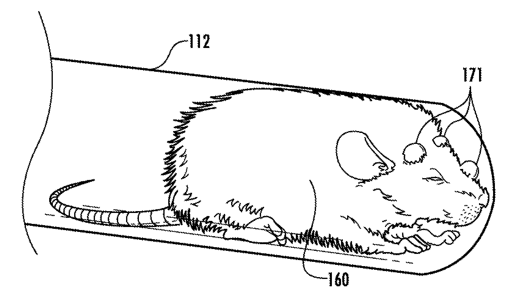
[0068]FIG. 1 shows an optical image of a mouse 160 fitted with three optical retro-reflective markers 171 on its head in a burrow 112. Images of the mouse with the retro reflectors from each camera and with tracking enabled are shown in FIG. 5. Tracking is shown by lines connecting the center of each marker 171. Also visible are reflections off the glass tube enclosure that have been ignored. The markers are outlined and numbered showing that they have been segmented and that correspondence has been determined. In this depiction, the lines between the markers 171 indicate that successful model fitting has been performed and that a full 3D transformation has been calculated between the camera reference frame and the model reference frame.

example # 2

Example #2

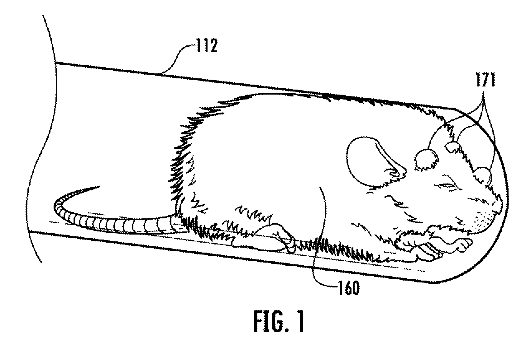
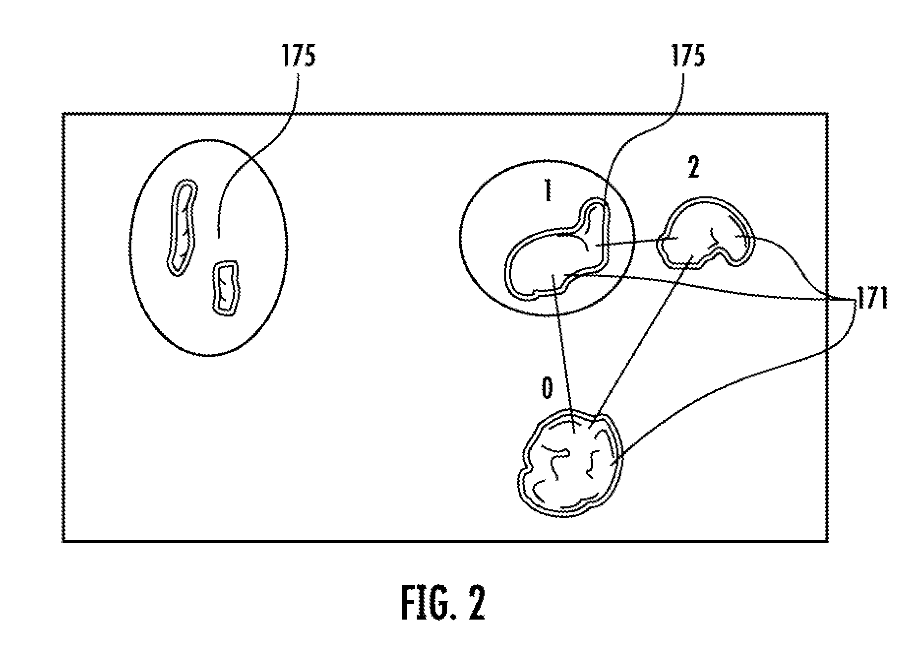
[0069]As described above, specular reflections 175 can make it difficult to discern markers 171. This problem is apparent from the specular reflections 175 in FIG. 2 and the illustration in FIG. 6. One way to eliminate specular reflections is the use of polarized light, polarizing filters, or both. Maulus' law for determining polarized light intensity is:

I(θ)=Io cos2(θ)  (1)

[0070]In Equation 1, I(θ) is the detected intensity, which is related to the input light intensity, Io, by a factor of the square of the cosine of the relative angle (θ) 200 between the input light state-of-polarization (SOP) axis 205 and the transmission axis 210 of the preceding polarizer (polarization filter), as shown in FIG. 7.

[0071]In FIG. 7, an unpolarized light beam of radiation, Is (e.g., infrared radiation) is passed through a linear polarizer 215 where it looses half of its original intensity. This can be explained by the assumption an unpolarized light source can be decomposed into two ortho...


PUM


Abstract

A method and related system for generating motion corrected tomographic images includes the steps of illuminating a region of interest (ROI) to be imaged being part of an unrestrained live subject and having at least three spaced apart optical markers thereon. At least one camera is used to obtain images of the markers. Motion data comprising 3D position and orientation of the markers relative to an initial reference position is then calculated. The at least three spaced apart optical markers and the at least one camera are sufficient in quantity and position to avoid multiple epipolar solutions. Motion corrected tomographic data obtained from the ROI using the motion data is then obtained, where motion corrected tomographic images obtained therefrom.

Description

CROSS-REFERENCE TO RELATED APPLICATIONS[0001]This application is a continuation-in-part of U.S. application Ser. No. 11 / 241,359, entitled “System and Method for Generating Motion Corrected Tomographic Images,” filed Sep. 30, 2005, the entirety of which is incorporated herein by reference.STATEMENT REGARDING FEDERALLY SPONSORED RESEARCH OR DEVELOPMENT[0002]The United States Government has rights in this invention pursuant to Contract No. DE-AC05-00OR22725 between the United States Department of Energy and UT-Battelle, LLC.BACKGROUND OF THE INVENTION[0003]Patient motion or motion of a living subject during imaging can cause image artifacts. The sources of motion include restlessness, as well as, processes such as respiration and heart beats, which can produce small movements due to pressure changes over the cardiac cycle. In some cases motion artifacts degrade the diagnostic value of an image.[0004]Efficient methods for testing new drugs are very important to the pharmaceutical indust...

Claims


Application Information

Patent Timeline
IPC IPC(8): A61B5/055
CPCA61B5/055A61B5/721A61B6/03A61B6/037A61B6/527A61B2503/40
Inventor GODDARD, JAMES S.BABA, JUSTIN S.
Owner UT BATTELLE LLC
Why Eureka
Try Eureka