Integrated system for producing composites

a composites and integrated technology, applied in the field of integrated systems for composites, can solve the problems of limited exchange of only a small number of essential signals and parameters between injection molding machines and pur plants, and the difference in the hardware components and the volume of software of injection molding machines, so as to improve the accuracy and reproducibility of dye metering, the effect of simple and quick change of dye modules

Inactive Publication Date: 2008-12-25
KRAUSSMAFFEI TECH GMBH
View PDF42 Cites 7 Cited by
  • Summary
  • Abstract
  • Description
  • Claims
  • Application Information

AI Technical Summary

Benefits of technology

[0029]One or more dye modules can be placed directly adjacent to the polyurethane mixing head for the purpose of dye metering. The dye lines can then be kept short, enabling a simple and quick change of the dye modules. The short dye lines also improve the precision and reproducibility of dye metering. Moreover, a dye change requires less cleaning due to the short length of the dye lines.
[0030]The clamping force on the mold can also be controlled as a function of certain parameters. For example, the clamping force can be controlled as a function of the PUR injection pressure in the mixing head. For example, venting at the beginning of a charge can be supported with a low clamping force. At the end of the charge, when the maximum pressure is reached, the clamping force can be increased to a maximal value in order to prevent overspraying.
[0031]Another advantage is temperature control of the mold during the operation of the polyurethane unit. For example, the temperature of the mold can be kept low when polyurethane is introduced. Low temperatures significantly delay the onset of the immediately starting cross-linking reaction. As a result, the filling process can be performed more slowly and at a lower pressure. The low pressure also prevents overspraying of the cavity. At the end of the charge, the mold is abruptly heated, thereby still achieving a rapid reaction time.

Problems solved by technology

There are significant differences between the hardware components and the volume of software of injection molding machines and PUR plants.
Moreover, an interface between, for example, an injection molding machine and a PUR plant is also limited to the exchange of only a small number of essential signals and parameters.
This complicates operation so that the plant can be operated only by well-trained personnel.
The control philosophy which is tailored to the various units must also be considered, which makes operating and monitoring the plant more difficult.

Method used


Image

  • Integrated system for producing composites
  • Integrated system for producing composites
  • Integrated system for producing composites

Examples


Embodiment Construction

[0038]Throughout all the figures, same or corresponding elements may generally be indicated by same reference numerals. These depicted embodiments are to be understood as illustrative of the invention and not as limiting in any way. It should also be understood that the figures are not necessarily to scale and that the embodiments are sometimes illustrated by graphic symbols, phantom lines, diagrammatic representations and fragmentary views. In certain instances, details which are not necessary for an understanding of the present invention or which render other details difficult to perceive may have been omitted.

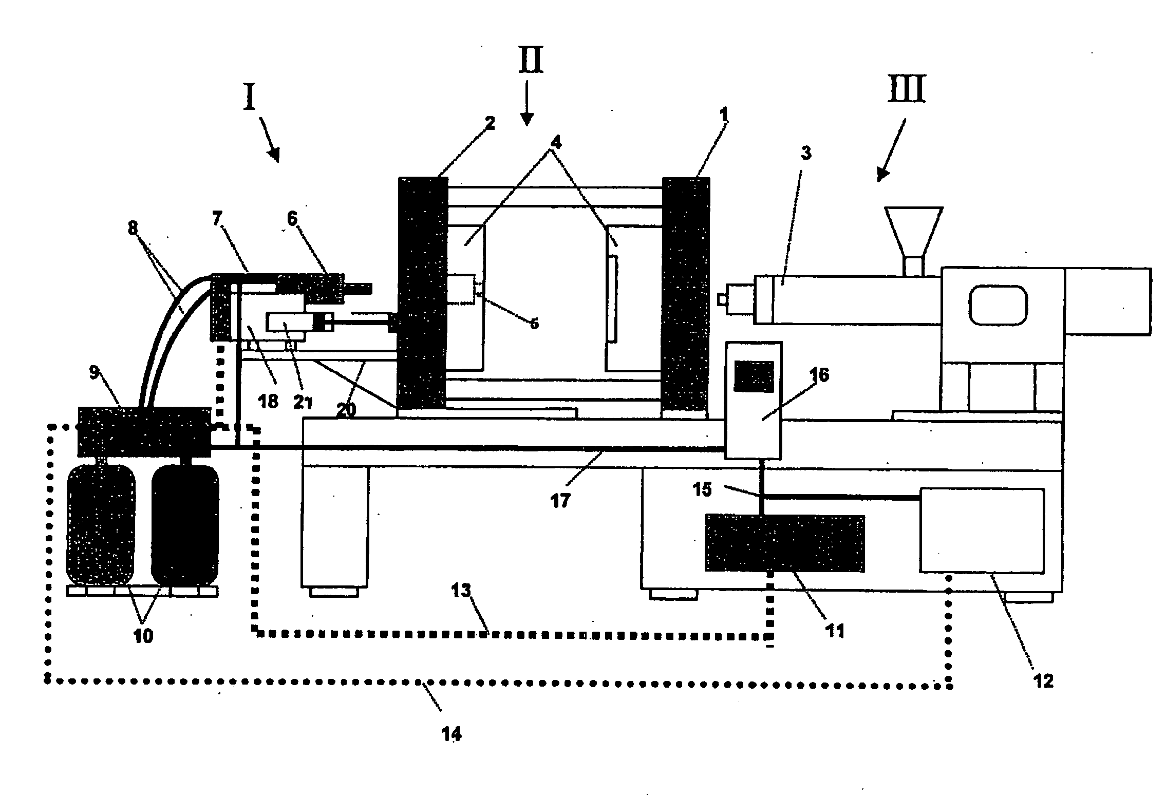
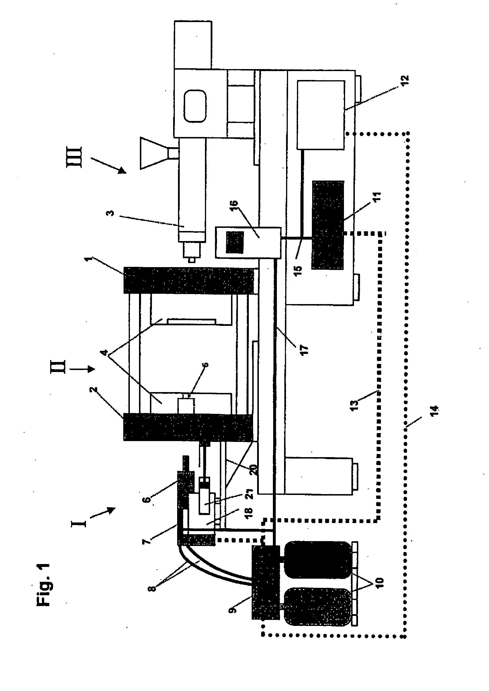
[0039]Turning now to the drawing, and in particular to FIG. 1, there is shown a schematic diagram of an integrated system according to the present invention. The integrated system includes essentially three large areas, namely a polyurethane unit I, a clamping unit II, and a plasticizing and injection unit III. The plasticizing and injection unit III is implemented in a conv...


PUM

PropertyMeasurementUnit
electricaaaaaaaaaa
torqueaaaaaaaaaa
speedaaaaaaaaaa

Abstract

An integrated system for production of composites includes at least one polyurethane unit with a mixing head for mixing a polyol component and an isocyanate component, at least one plasticizing and injection unit, which is suitable for the melting and subsequent injection of a thermoplastic material, and one clamping unit to receive at least one mold. The plasticizing and injection unit and the polyurethane unit can each introduce material to be processed into a mold cavity within the clamping unit. In order to implement a unitary strategy of control and regulation and a unitary approach to operation of this type of integrated system apparatus, a single central control unit and at least one common supply device are provided, with the central control unit being connected at least with the at least one supply device. The at least one common supply device acts at least on both the polyurethane unit and the plasticizing and injection unit.

Description

CROSS-REFERENCES TO RELATED APPLICATIONS[0001]This application is a continuation of prior filed copending PCT International application no. PCT / EP2007 / 050408, filed Jan. 16, 2007, which designated the United States and has been published but not in English as International Publication No. WO 2007 / 101738 and on which priority is claimed under 35U.S.C. §120, and which claims the priority of German Patent Application, Serial No. 10 2006 009 900.1, filed Mar. 3, 2006, pursuant to 35 U.S.C. 119(a)-(d), the contents of which are incorporated herein by reference in its entirety as if fully set forth herein.BACKGROUND OF THE INVENTION[0002]The present invention relates, in general, to an integrated system for producing composites.[0003]Combined systems used to date to make plastic composites, in particular composites made from a combination of a polyurethane material with a thermoplastic material include various units which are arranged side-by-side and operated separately. For example, a p...

Claims


Application Information

Patent Timeline
Patent Type & Authority Applications(United States)
IPC IPC(8): B29C45/17
CPCB29C45/045B29C45/16B29C45/1628B29K2075/00B29C45/82B29C67/246B29C45/76B29C67/24
Inventor GRUBER, MARCO
Owner KRAUSSMAFFEI TECH GMBH
Why Eureka
Try Eureka