Intelligent MEA for fuel cell

Active Publication Date: 2008-12-25
HYUNDAI MOTOR CO LTD
View PDF4 Cites 4 Cited by
  • Summary
  • Abstract
  • Description
  • Claims
  • Application Information

AI Technical Summary

Benefits of technology

[0029]The present invention has been made in an effort to solve the above problems, and an object of the present invention is to provide an intelligent membrane electrode assembly (MEA) for fuel cell in which a flexible PCB including an electrical heating element, temperature sensors and electrical contacts is mounted to an MEA, which can easily measure the voltage of the unit cells constituting the fuel cell stack and the resistance and temperature of the MEA and prevent heat transfer from an outside low-temperature heat source to a catalyst layer of the MEA during preservation and operation of the fuel cell stack at low temperature.
[0036]Suitably, a flexible PCB fixing film is provided on the surface of the ion exchange membrane support film so as to cover the flexible PCB in order to reinforce the bonding force between the flexible PCB and the ion exchange membrane support film of the MEA.

Problems solved by technology

As mentioned above, since the fuel cell stack for vehicle is composed of several hundred unit cells, it takes a lot of time to form a voltage terminal in each unit cell after assembling the stack, which is considered as a problem that affects the production rate in mass production of the fuel cell stack.
However, such a structure has some drawbacks in that the separators may be damaged by vibration and impact generated during vehicle driving as shown in the photographs of FIGS. 3 and 4.
Moreover, the contact property with respect to the separator may be deteriorated and the terminals may be separated therefrom.
Furthermore, it takes much time to sequentially insert the terminals into the grooves.
However, the above-described prior art technologies have some common problems in that, as the interval of the separators is irregular, in case of a fuel cell stack composed of a small number of unit cells, it is possible to design a connector having elastic contact terminals arranged in series in view of manufacturing tolerance of the fuel cell stack and mount the thus designed connector to a separator; however, in case of a fuel cell stack composed of at least 200 unit cells, it is very difficult to design the contact terminals due to manufacturing tolerance of the whole length of the stack.
The key problem to be solved to achieve the mass production of the fuel cell stack is startability at a low temperature below the freezing point.
Under low temperature conditions, if the ion conductivity of the ion exchange membrane 20 is sharply decreased, the performance of the fuel cell stack is deteriorated.
Accordingly, starting the fuel cell at a temperature below the freezing point becomes a critical issue in many companies and research institutes related to the fuel cell.
However, the amount of energy generated in the fuel cell stack itself, while water, heat and electricity are generated by the reaction between hydrogen and oxygen, is not enough to raise the temperature of the stack above the freezing point.
However, although the above-described prior art methods heat end cells exposed to the cold air to raise the temperature thereof, they cannot raise the temperature of the entire fuel cell stack.
Moreover, the method of heating a coolant by electrical energy generated at the initial stage of the operation of the fuel cell stack or using a heat exchanger requires a lot of time to heat an intermediate material and is inefficient in view of the efficiency of the heat exchanger.
Furthermore, the method of wrapping the fuel cell stack with a heat insulating material is effective to prevent the temperature of the stack from falling after driving at a low temperature and to shorten the time required to raise the temperature of the stack above the freezing point by preventing heat generated in the stack from being transferred to the air; however, it cannot actively raise the temperature of the stack.

Method used


Image

  • Intelligent MEA for fuel cell
  • Intelligent MEA for fuel cell
  • Intelligent MEA for fuel cell

Examples


Embodiment Construction

[0050]Reference will now be made in detail to the preferred embodiment of the present invention, examples of which are illustrated in the drawings attached hereinafter, wherein like reference numerals refer to like elements throughout. The embodiments are described below so as to explain the present invention by referring to the figures.

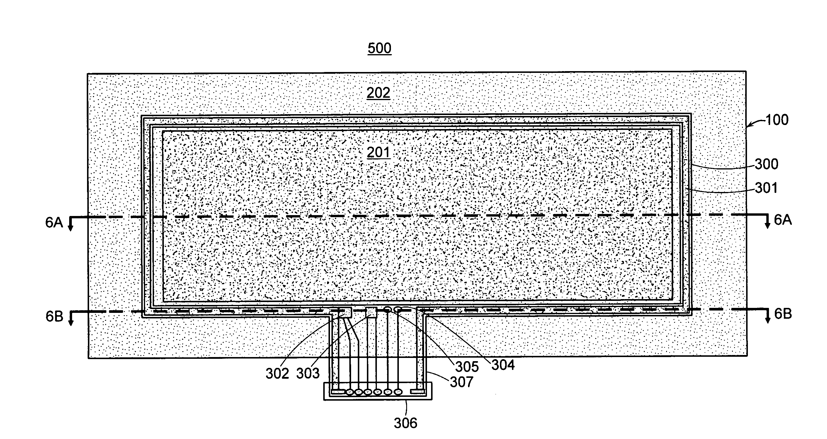
[0051]FIG. 5 is a plan view illustrating a flexible PCB for an intelligent MEA in accordance with an exemplary embodiment the present invention, and FIG. 6 is a plan view and a cross-sectional view illustrating an intelligent MEA on which the flexible PCB of FIG. 5 is mounted.

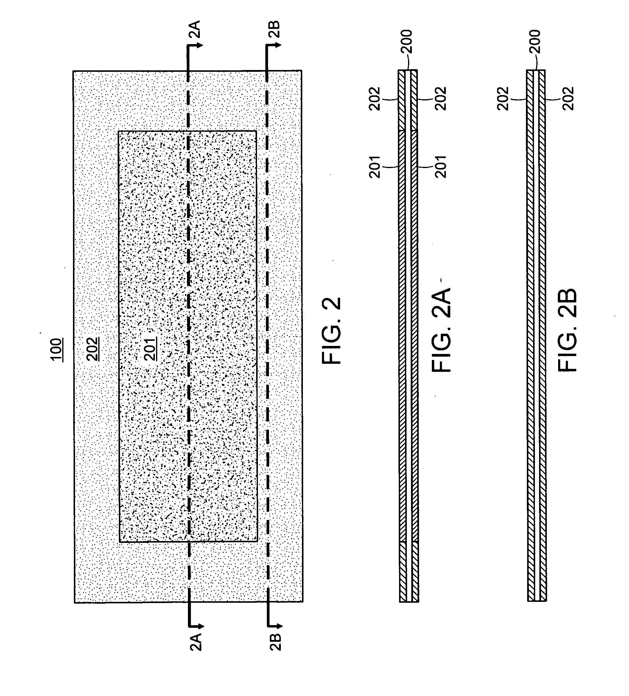
[0052]The intelligent MEA in accordance with the present invention includes an ordinary membrane electrode assembly (MEA) 100, in which a catalyst layer 201 is coated on both sides of an ion exchange membrane 200 (or an electrolyte membrane), and a flexible PCB 400 mounted on the MEA 100. Especially, the flexible PCB 400 is characterized in that an electrical heating element 301...


PUM


Abstract

The present invention provides an intelligent MEA for fuel cell including means for easily measuring the voltage of unit cells and means for preventing heat transfer from an outside low-temperature heat source to a catalyst layer of the MEA during operation of the fuel cell stack at low temperature.For this, the present invention provides n intelligent membrane electrode assembly (MEA) for fuel cell, including: an MEA in which a catalyst layer is coated on both sides of an ion exchange membrane, and an ion exchange membrane support film is attached on both sides of an edge portion of the ion exchange membrane; a flexible printed circuit board (PCB) mounted on one surface of the ion exchange membrane support film along the outer line of the catalyst layer of the MEA; a PCB terminal formed on one end of the flexible PCB; and a connector connected to the PCB terminal to communicate with an external controller, wherein the flexible PCB includes an electrical heating element, an electrical heating element temperature sensor for measuring the temperature of the electrical heating element, an MEA temperature sensor for measuring the temperature of the MEA, an electrical contact for measuring the resistance of unit cells, and an electrical contact for measuring the voltage of the unit cells, formed in a predetermined arrangement to communicate with the PCB terminal.

Description

CROSS-REFERENCE TO RELATED APPLICATION[0001]This application claims under 35 U.S.C. §119(a) on Korean Patent Application No. 10-2007-0059866, filed on Jun. 19, 2007, the entire contents of which are incorporated herein by reference.BACKGROUND[0002](a) Technical Field[0003]The present invention relates to an intelligent membrane electrode assembly (MEA) for fuel cell. More particularly, the present invention relates to an intelligent MEA for fuel cell that can easily measure the voltage of unit cells and prevent heat transfer from an outside low-temperature heat source to a catalyst layer of the MEA during preservation and operation of the fuel cell stack at low temperature.[0004](b) Background Art[0005]A fuel cell stack, which is a main power source of a fuel cell vehicle, is a device that generates electricity by an electrochemical reaction between oxygen in the air and hydrogen supplied from fuel. The fuel cell stack applied to a vehicle is composed of several hundred unit cells, ...

Claims


Application Information

Patent Timeline
IPC IPC(8): H01M8/02
CPCH01M8/0247H01M8/04007H01M8/04037H01M8/04253H01M8/04365H01M8/04552H01M8/04641H01M8/1004H01M2250/20Y02T90/32Y02E60/521Y02E60/50Y02T90/40H01M4/86H01M8/04
Inventor KIM, SAE HOONLEE, YOUNG-HYUN
Owner HYUNDAI MOTOR CO LTD
Why Eureka
Try Eureka