
Safety workbench and method for the calibration thereof

Active Publication Date: 2008-12-25
THERMO ELECTRONICS LED GMBH
View PDF14 Cites 10 Cited by
  • Summary
  • Abstract
  • Description
  • Claims
  • Application Information

AI Technical Summary

Benefits of technology

[0011]The object of the present invention is accordingly to specify a safety workbench, which operates reliably within correctly calibrated parameter ranges independently of its installation location and with which it is ensured it is correctly put into operation easily and cost-effectively even without the aid of service personnel.
[0036]After completing calibration, it is ensured that the safety workbench also operates on the basis of device parameters and alarm limits exactly tuned to the working location at its new working location. In addition, a service technician may be dispensed with when putting the safety workbench into operation. However, if a service technician is present when putting it into operation, his work is correspondingly made easier and the time expenditure is significantly reduced. Depending on the way in which the calibration is executed, work may also be saved at the factory, because all parameter values no longer have to be measured and stored already at the factory. For example, the flow velocities corresponding to the alarm limits may also be measured for the first time by the user of the safety workbench at the working location.

Problems solved by technology

For example, the starting setpoint value may be provided in the form of a specific fan performance—such as a specific speed or a specific power consumption—which in turn results in a specific flow velocity of the air flow delivered by the fan, however.

Method used


Image

  • Safety workbench and method for the calibration thereof
  • Safety workbench and method for the calibration thereof
  • Safety workbench and method for the calibration thereof

Examples


Embodiment Construction

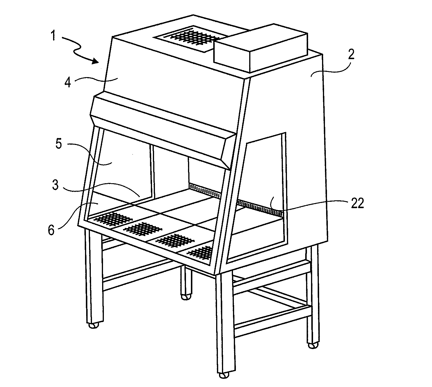
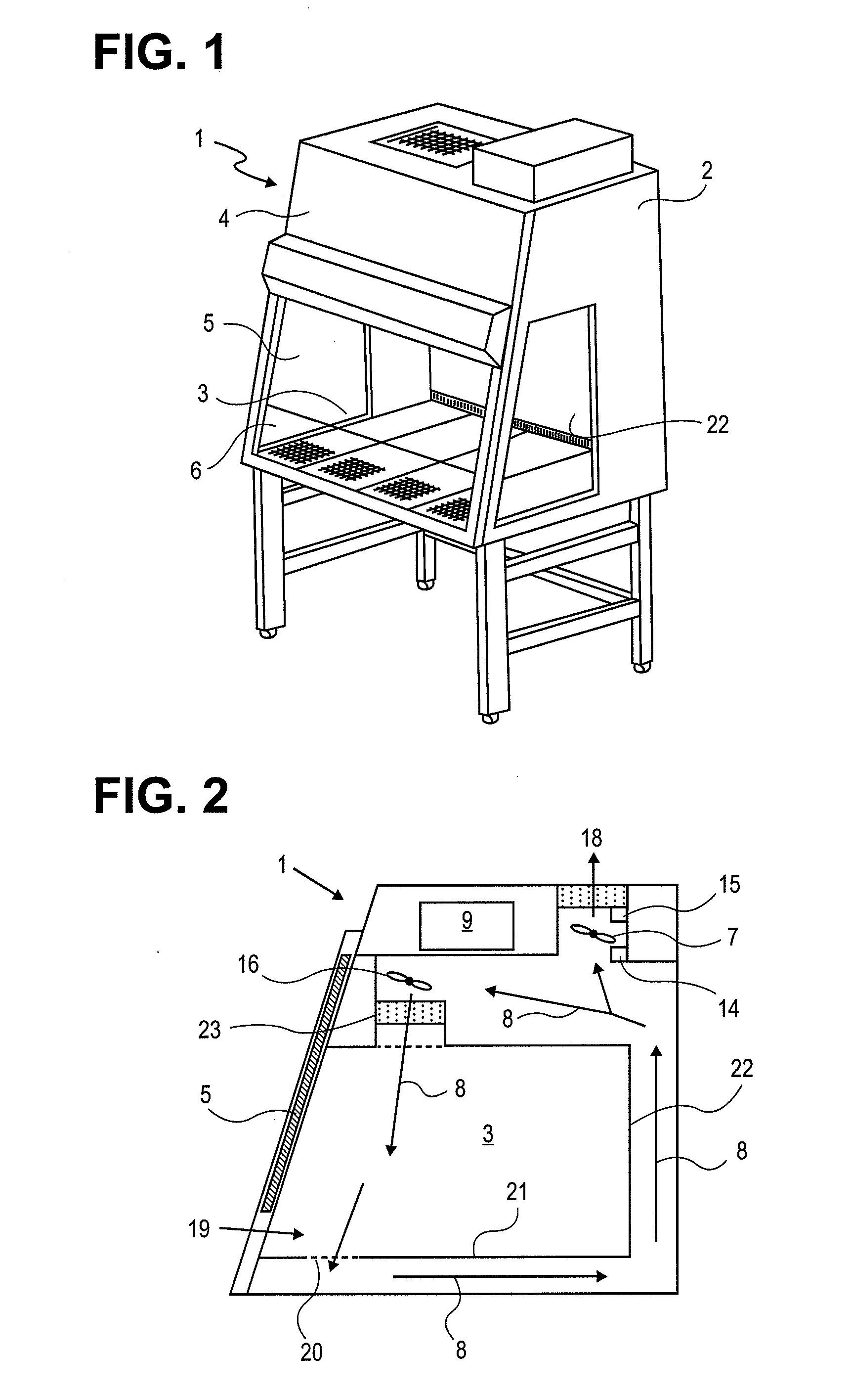
[0041]FIGS. 1 and 2 show a safety workbench (1) according to the present invention, which may be used for processing microbiological cultures, for example. In its basic construction, the safety workbench (1) corresponds to that known from the prior art. The safety workbench has a housing (2), which encloses a working inner chamber (3). An adjustable front pane (5) is situated on the housing front side (4), which is mounted in such a way that it may be pushed up and down essentially parallel to the housing front side. By pushing down the front pane (5), the work opening (6) located on the housing front side may be made smaller or closed entirely. The height of the work opening (6) thus results from the gap between the bottom side of the front pane (5) and the working chamber floor plate of the housing (2).

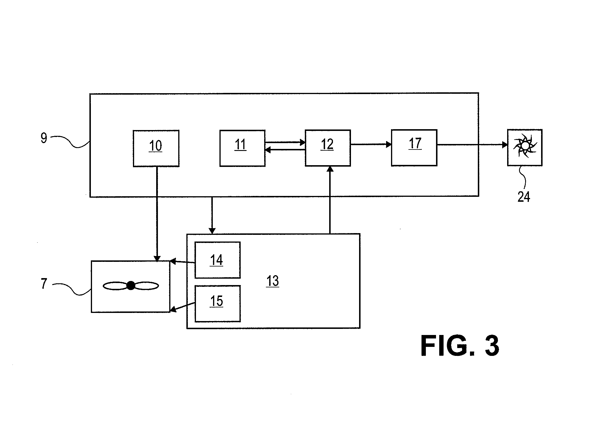
[0042]Two fans are provided in the safety workbench (1), namely an exhaust air fan (7), which conveys a specific volume component of the air (8) delivered into the interior of the s...


PUM


Abstract

The present invention relates to a safety workbench, in which, for the purpose of calibrating the safety workbench before beginning regular operation, a device control unit is implemented to cause measurement means to ascertain an actual measured value, which is representative of a flow velocity achieved at normal fan performance, an analysis unit is implemented to compare the actual measured value to a starting setpoint value and, in case of an established deviation, to correct a stored starting limiting value in accordance with the deviation, or means for controlling the fan are implemented to operate the fan at a fan performance corresponding to a stored starting limiting value, a device control unit is implemented to cause the measurement means to ascertain an actual limiting measured value which is representative of the flow velocity achieved at the set fan performance, and a storage unit is implemented to store the actual limiting measured value as the corrected limiting value. Furthermore, the present invention relates to a corresponding calibration method.

Description

CROSS-REFERENCE TO RELATED APPLICATIONS[0001]This application is based upon and claims the benefit of priority from prior German Patent Application No. 10 2006 060 713.9, filed Dec. 21, 2006, the entire contents of which are incorporated herein by reference.BACKGROUND OF THE INVENTION[0002]The present invention relates to a safety workbench according to the preamble of Claim 1 and a method for the automatic calibration of a safety workbench of this type. Safety workbenches, and particularly those for processing microbiological samples, as are described, for example, in DE 44 41 784 C2, protect from contamination by bioaerosols, which occur and are released in microbiological work. The contaminated air flow is continued as a directed air flow and conducted over filters, which hold back the contaminants from the air flow, with the aid of at least one fan within the safety workbenches.[0003]Safety workbenches differ in their safety precautions and are constructed, tested, and licensed ...

Claims


Application Information

Patent Timeline
IPC IPC(8): B08B15/02B01L9/02
CPCB08B15/023
Inventor ROSS, GERDREINHARDT, HEIKORUPP, OLIVERBRACHTL, STEFANSTAHL, HERMANN
Owner THERMO ELECTRONICS LED GMBH
Learn More