Downward angle settable hydraulic tensioner

a hydraulic tensioner and downward angle technology, applied in the direction of belts/chains/gearrings, mechanical equipment, belts/chains/gearrings, etc., can solve the problems of excessive backlash, abnormal sound generation, impaired damping effect of the tensioner, etc., to prevent the backlash of timing chains, the damping performance is maintained, and the plunger is rapidly balanced

Active Publication Date: 2008-12-25
TSUBAKIMOTO CHAIN CO
View PDF11 Cites 5 Cited by
  • Summary
  • Abstract
  • Description
  • Claims
  • Application Information

AI Technical Summary

Benefits of technology

[0014]When an engine in which the tensioner is incorporated with its plunger protruding obliquely downward is inoperative for a long period of time, even if oil leaks by gravity from the second high pressure chamber surrounding the rear portion of the sleeve through the slight gap between the plunger-accommodating hole and the plunger, and outside air is drawn into the second high pressure chamber, the outside air does not enter the first high pressure chamber, which is positioned lower than the second high pressure chamber. The damping action resulting from leakage of oil though a gap between the sleeve and the inner wall of the plunger is unimpaired, and backlash of the timing chain upon starting of the engine and abnormal sounds are prevented.
[0015]Furthermore, since the plunger slides between the inner circumferential wall of the plunger-accommodating hole and the outer circumferential surface of the sleeve, a labyrinth is formed which is composed of a first gap between the outer circumferential surface of the sleeve and the cylindrical inner wall of the plunger, and a second gap between the outer circumferential surface of the plunger and the inner circumferential surface of the plunger-accommodating hole. Thus oil leakage from the inside of the tensioner is suppressed and oil can be retained the tensioner over a long period of time.
[0016]The changes in volumes of the first and second high pressure chambers differ as the plunger moves. Consequently, a difference can be generated between the pressures in the two chambers. Since oil pressure balance accelerating means are provided to balance the pressure between the first and second high pressure chambers, the oil pressure in the second high pressure chamber is rapidly harmonized with the oil pressure in the first high pressure chamber at the time of engine start-up, and maintained during subsequent engine operation. Thus, the ability of the plunger to prevent timing chain backlash on engine-startup, and to follow tension changes in the timing chain during subsequent engine and is remarkably improved.
[0017]Where the oil pressure balance accelerating means comprises a passage formed on the outer circumferential surface of the sleeve, providing oil communication between the first high pressure chamber and the second high pressure chamber, a difference in the oil pressures in the two chambers resulting from different volume changes that occur as the plunger moves, is rapidly balanced so that the tensioner's damping performance is maintained. Thus the tensioner maintains its ability to exert a damping effect on changes in chain tension, both at the time of engine start-up, and during subsequent engine operation.
[0018]When the means for accelerating comprises a passage formed in the hollow sleeve adjacent its first end, providing oil communication between the second high pressure chamber and the oil reservoir in the interior of the sleeve, balancing does not take place by direct communication between the first and second chambers. However, on retraction of the plunger, excessive pressure in the second chamber is prevented by flow of oil from the second chamber into the reservoir. Similarly, when the plunger moves in the protruding direction, an excessive drop in pressure within the second chamber is prevented by flow of oil from the reservoir into the second chamber. In this way, the pressure in the second chamber is kept more nearly equal to the pressure in the first chamber, and the maximum damping effect of the tensioner on a change in chain tension, at the time of engine start-up and during the subsequent engine operation, can be exhibited.

Problems solved by technology

Because the accumulated air is compressible, the damping effect of the tensioner is impaired, backlash of the timing chain is not suppressed, and abnormal sounds are generated.
Damage to the timing chain can result from excessive backlash.
Additionally, oil consumption in the tensioner is increased, and the oil pump must supply an increased amount of oil to the tensioner.

Method used


Image

  • Downward angle settable hydraulic tensioner
  • Downward angle settable hydraulic tensioner
  • Downward angle settable hydraulic tensioner

Examples


Embodiment Construction

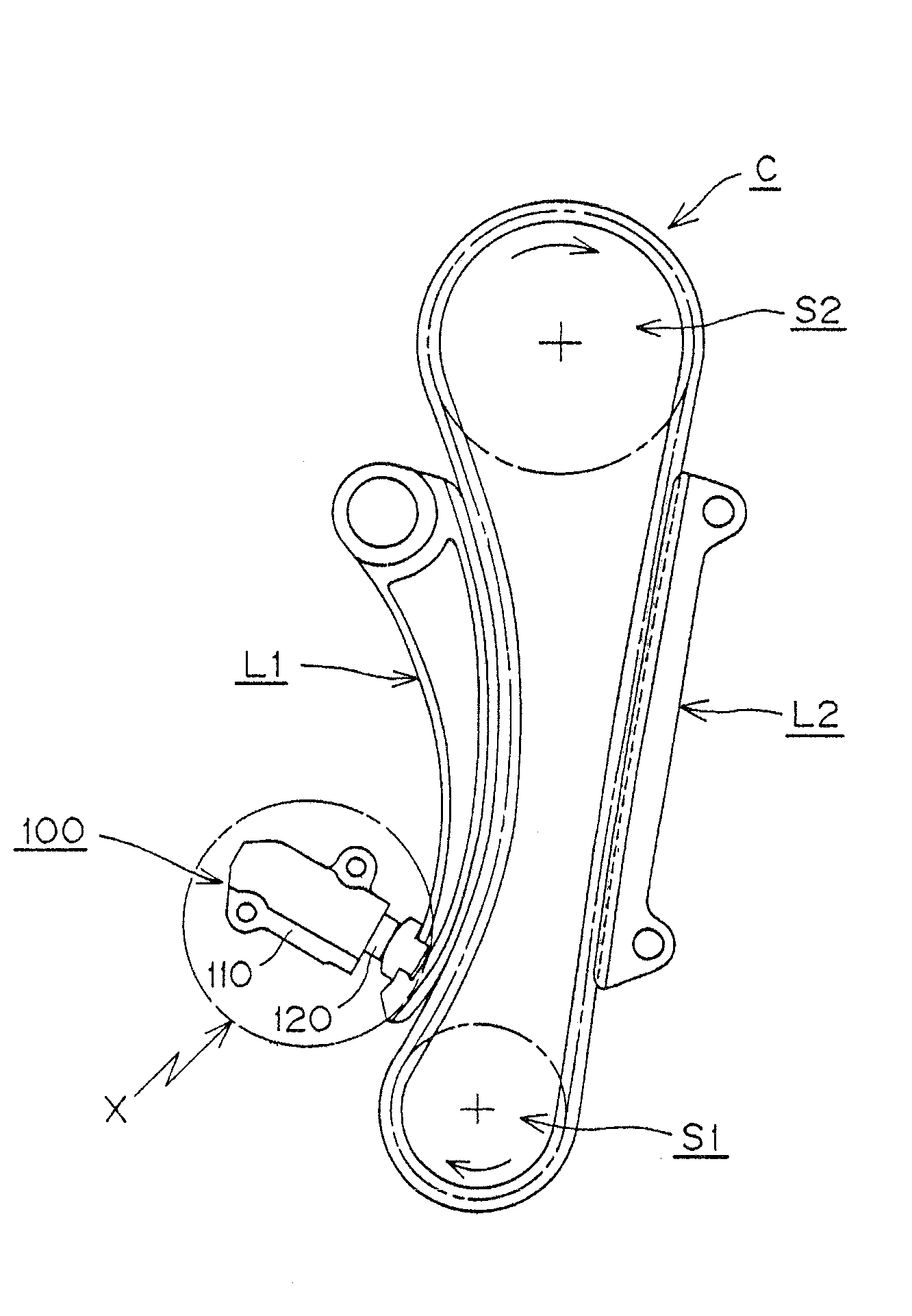
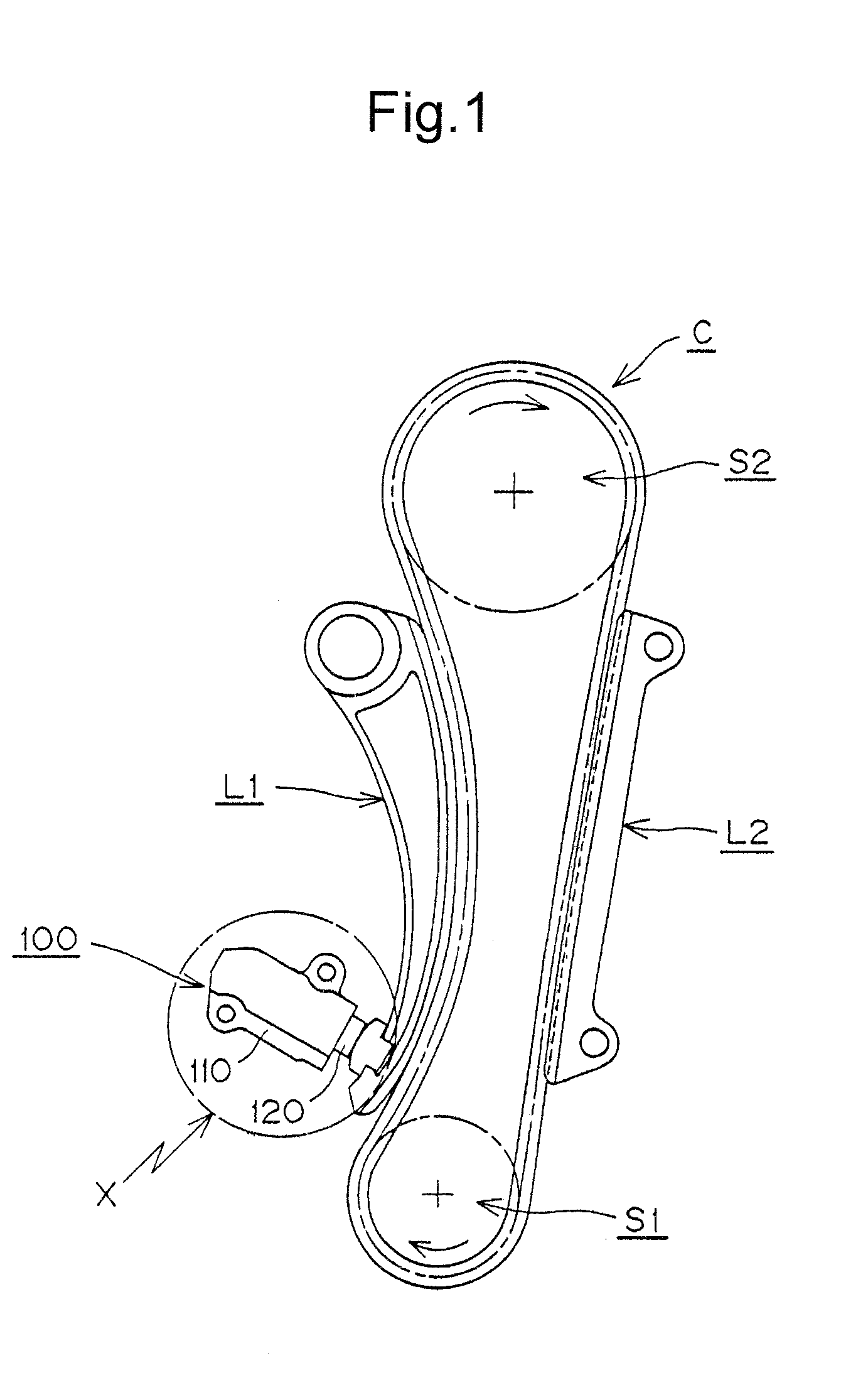
[0042]As shown in FIGS. 1 and 2, a downward angle settable hydraulic tensioner 100, according to a first embodiment of the invention, is mounted on an engine body on the slack side of a timing chain C engaged with a driving sprocket S1 rotated by a crankshaft, and a driven sprocket S2 fixed to a camshaft. The sprockets rotate in the direction indicated by the arrows in FIG. 1. The plunger 120 of the tensioner protrudes extendibly and retractably from the front of the housing 110. The plunger engages a pivoted lever L1, on which the slack slide of the chain slides, at a location spaced from the lever's pivot axis, thereby maintaining tension in the chain. A fixed guide L2 is in sliding engagement with the tension side of the chain.

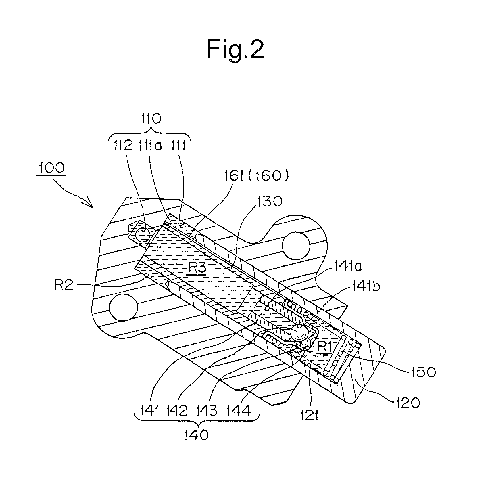
[0043]As shown in FIG. 2, the plunger 120 is slidable in, and protrudes from, a plunger-accommodating hole 111 formed in a tensioner housing 110 and having a closed end. A cylindrical hollow portion 121 is formed inside the plunger, having an opening facing...


PUM


Abstract

In a hydraulic chain tensioner having a housing, a hollow plunger slidable in a plunger-accommodating hole in the housing, and a hollow sleeve extending into the plunger from a bottom of the plunger-accommodating hole, and a check valve mounted at the opposite end of the sleeve, a passage is provided on the outer surface of the sleeve to accelerate the balance of pressure between a first high pressure chamber between the check valve and the protruding end of the plunger and a second high pressure chamber between the inner end of the plunger and the bottom of the plunger-accommodating hole. In an alternative embodiment, balance is accelerated by communication between the second high pressure chamber and an oil reservoir inside the sleeve on the upstream side of the check valve.

Description

CROSS-REFERENCE TO RELATED APPLICATION[0001]This application claims priority on the basis of Japanese patent application 2007-161310, filed Jun. 19, 2007. The disclosure of Japanese application 2007-161310 is hereby incorporated by reference.FIELD OF THE INVENTION[0002]The invention relates to hydraulic tensioners of the kind used for applying proper tension to a timing belt, a timing chain, or the like in a vehicle engine. The invention relates more specifically to a tensioner that can be set so that its plunger can protrude not only horizontally, but also at an oblique upward angle or at an oblique downward angle.BACKGROUND OF THE INVENTION[0003]Hydraulic tensioners have been widely used for suppressing vibration and maintaining proper tension in traveling transmission media such as engine timing chains which transmit power from a crankshaft to one or more valve-operating camshafts in an internal combustion engine.[0004]A conventional hydraulic tensioner is described in United Sta...

Claims


Application Information

Patent Timeline
Patent Type & Authority Applications(United States)
IPC IPC(8): F16H7/08
CPCF16H7/0848F16H2007/0806F16H2007/0812F16H2007/0859F16H7/08
Inventor NAMIE, TSUTOMUHASHIMOTO, HIROSHIMIYAKE, HIROYUKI
Owner TSUBAKIMOTO CHAIN CO
Why Eureka
Try Eureka