Rock Core Removal Method and Apparatus

a technology for rock cores and sampling, applied in the direction of earth drilling tools, drilling accessories, borehole/well accessories, etc., can solve the problems of increasing the size of the sample, reducing the accuracy of the sample, so as to reduce the diameter of the collet tube collecting end, the effect of simplifying the design

Inactive Publication Date: 2009-01-01
MYRICK THOMAS M
View PDF7 Cites 16 Cited by
  • Summary
  • Abstract
  • Description
  • Claims
  • Application Information

AI Technical Summary

Benefits of technology

[0012]Generally, a preferred embodiment of this invention comprises a coaxial arrangement of a cylindrical collet tube located within a cylindrical ground tube which is located within a cylindrical drill tube with a drill bit affixed to one end. In a preferred embodiment, the drill bit is connected to the drill tube through a quick-change mechanism. The collet tube has constricting fingers near its collecting end which are able to flex inward towards the center axis in order to decrease the diameter of the collet tube's collecting end. In a preferred embodiment, features in the collet tube, ground tube, or both tubes cause the collet tube's constricting fingers to flex towards the center axis when the collet tube is moved upwards a small distance with respect to the ground tube, thus allowing the collet tube to grip a core sample that has been drilled.
[0013]In multiple preferred embodiments, the collet tube can be raised with respect to the ground tube to grab the core sample, and then, with respect to the drill tube and drill bit, both the collet tube and ground tube can be (1) raised to break off the core sample solely through tension, (2) rotated until the core sample is broken off solely through torsion, or (3) raised and rotated to break off the core sample through a combination of tension and torsion. A preferred embodiment may allow for the user to adjust the desired proportion of tension to torsion used to break the core sample. An alternate preferred embodiment would allow this apparatus to be manufactured with a specific ratio of tension to torsion. In a preferred embodiment, the same movement actuator that causes the collet tube to grip the core also acts to rotate and raise the collet tube and ground tube in the core sample break-off process.
[0014]In a preferred embodiment, an ejection rod is used to push the core sample out of the collet tube after the collet tube is lowered with respect to the ground tube in order to release its grip on the core sample. The ejection rod also serves to change operating modes of the movement actuator that first causes the collet tube to grip the core sample and later rotates and raises the collet tube and ground tube combination. This embodiment would eliminate the need for additional actuators and simplify the design.
[0015]During the drilling process, the collet tube and ground tube are rotationally secured so as not to rotate with the drill tube and drill bit. The collet tube and ground tube thus act as non-rotating “sleeves” which protect the core sample from inadvertent breakage while drilling. The protection of the core sample during drilling as well as the unique break-off method allows for the retrieval of much longer core samples than permitted by prior art methods and devices. Additionally, the non-rotating “sleeves” also protect the entire drilling and core removal apparatus from the danger of dust buildup. At the same time, the ground tube also acts as a stable bushing support for the drill bit.
[0016]In a further preferred embodiment, a drill bit quick-change mechanism is employed to allow for rapid changing of stuck, broken, worn, or different drill bits in a reliable autonomous fashion without the need for additional actuators. In multiple embodiments, the extra range of movement of the ground tube that is not employed in the core break-off process may be used to actuate the quick-change mechanism. In a preferred embodiment, the attachment end of the drill tube has small tabbed features capable of moving outward so as to engage a groove in the inner diameter of the drill bit. In this preferred embodiment, the ground tube generally forces the drill tube's tabbed features outwards into the grooved recesses of the drill bit. In this preferred embodiment, the ground tube is shaped so that when it is moved through its extra range of motion, it allows the drill tube's tabbed features to move inward and release the drill bit. Preferred embodiments may use drill bit quick-change mechanisms that secure the drill bit both vertically and rotationally or only vertically. If the drill bit quick-change mechanism only secures the drill bit vertically, an alternate method, such as keyed features, must be used to rotationally couple the drill bit and drill tube. Such preferred embodiments would allow the drill tube, collet tube, ground tube, core sample, and other parts to be saved and retrieved even if the drill bit becomes stuck in the hole it is drilling.

Problems solved by technology

It is often impractical to drill completely through the rock to be sampled.
When obtaining a core sample by drilling to the desired depth and rocking the drill shaft back and forth, several problems arise.
As the cutting annulus size increases, the drill tends to operate slower, work less efficiently, and generate more dust.
Soon it becomes impractical to use this method of core sample removal at any depth greater than several drill diameters.
Drill shaft flexing will also detract from the available rocking angle.
Some current core sampling techniques can therefore become difficult in sandy or soft surroundings.
Additionally, in extraterrestrial environments, many of the weight, power, and cost restraints make undesirable a drilling apparatus requiring such external loads reacting to ground.
Some current core sample removal techniques subject the core sample to strong, rotational friction forces while drilling, which can result in inadvertent, premature core breakage.
These premature breakages can cause the core sample to become jammed within the collection device.
Additionally, the rotational friction forces against the core sample may cause particles to break off of the core sample and accumulate as dust.
This dust may clog different parts of the drilling and core removal apparatus rendering either certain parts inoperable or possibly rendering the entire drilling and core removal apparatus inoperable.
Some current core sample removal techniques do not provide for a drill bit quick-change mechanism.
Some current core sample removal techniques run the risk of having the drill tube or possibly the entire drilling mechanism rendered inoperable and immobile if the drill bit gets clogged, broken, or otherwise stuck while still in the hole.
Some current core sample removal techniques provide a quick-change means for the drill bit, but are unable to obtain the core sample if the drill bit must be released during a drilling operation.
Some current core sample removal techniques do not provide for a stable bushing support to the drill bit during the drilling process.
Some current core sample removal techniques are not reliable enough to be run autonomously.
The large number of moving parts can increase the cost of the mechanisms, impart a loss of drilling efficiency, increase the cost of necessary repairs, and increase the downtime required for repairs.
Additionally, in extraterrestrial environments, such a large number of moving parts may be unable to comply with weight, power, and cost restrictions.

Method used


Image

  • Rock Core Removal Method and Apparatus
  • Rock Core Removal Method and Apparatus
  • Rock Core Removal Method and Apparatus

Examples


Embodiment Construction

[0034]The following description is merely exemplary in nature and is not intended to limit the present disclosure, application, or uses. It should be understood that throughout the drawings, corresponding reference numerals indicate like or corresponding parts and features.

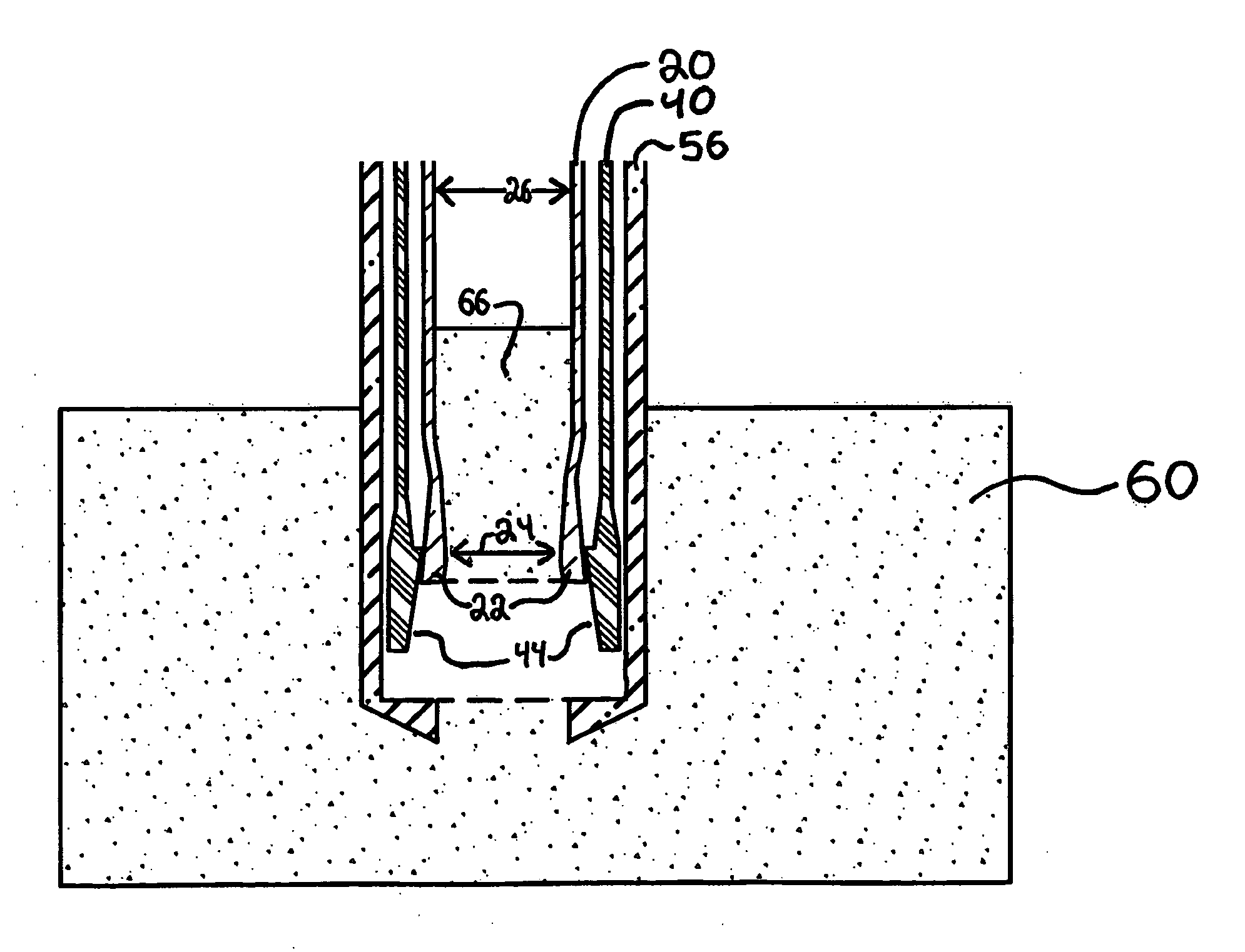
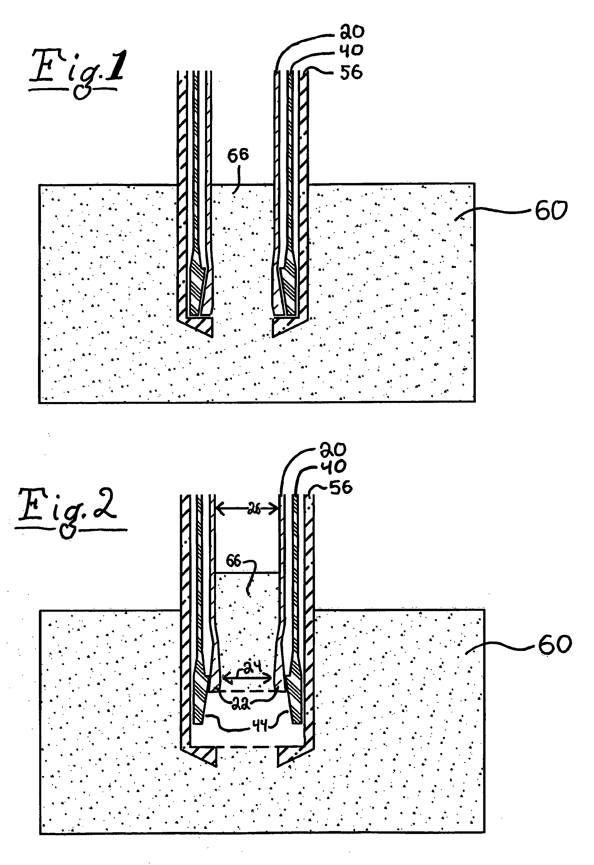
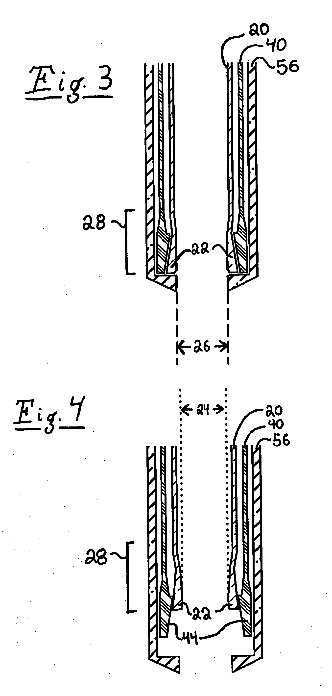
[0035]Referring to FIG. 3, the collecting end of the collet core removal apparatus is shown, made up of a collet tube 20 located within a ground tube 40 which is further located within a drill tube 50. Referring to FIG. 11, the collet tube 20 has a collet tube driving end 21. The ground tube 40 also has a ground tube driving end 41.

[0036]Referring back to FIG. 3, the collet tube collecting end 28 has constricting fingers 22 that are capable of flexing inwards radially. Referring to FIG. 7, the constricting fingers 22 of the collet tube 20 can vary in design, material, and number. One preferred embodiment which is depicted in FIG. 7 shows the constricting fingers 22 formed by slats of collet tube material. It is re...


PUM


Abstract

A rock core removal method and apparatus allows efficient, safe, and reliable removal of a rock core sample. An inner collet tube and an outer ground tube, within a drill tube, protect the core sample during drilling. At depth, the collet tube is raised with respect to the ground tube so that the conical wall of the ground tube pushes constricting fingers on the collet tube inward, gripping the core sample within. The collet tube and ground tube are then raised, rotated, or raised and rotated, applying the necessary force to break the core sample off of the substrate. After retracting the tubes, the collet tube is lowered with respect to the ground tube to release the core sample. An ejection rod then pushes the core sample out of the collet tube. The ground tube may also act as the actuating means for a quick-change drill-bit release feature.

Description

[0001]This U.S. patent application claims the priority from U.S. Provisional Application No. 60 / 937,142 on Jun. 26, 2007 by the same inventor having the title “Collet Core Removal.”BACKGROUND ART[0002]This invention generally relates to a method and apparatus for taking a rock core drilling sample. In particular, the invention is directed to an improved method of taking core samples from base rock at any depth using simple elements in a controlled and reliable fashion. Some preferred embodiments of this invention are particularly useful for removing rock core samples in extraterrestrial environments.[0003]Some current core sample removal techniques consist of drilling completely through the base rock in order to obtain a core sample. It is often impractical to drill completely through the rock to be sampled. The depth of the base rock may not be known, or if it is known, may be far deeper than the desired sampling depth.[0004]Some current core sample removal techniques consist of dr...

Claims


Application Information

Patent Timeline
Patent Type & Authority Applications(United States)
IPC IPC(8): E21B49/02E21B25/10
CPCE21B25/12E21B25/005
Inventor MYRICK, THOMAS M.
Owner MYRICK THOMAS M
Why Eureka
Try Eureka