Microwave Gasification, Pyrolysis and Recycling of Waste and Other Organic Materials

a technology of pyrolysis and waste, which is applied in the direction of charging devices, energy inputs, transportation and packaging, etc., can solve the problems of increasing waste accumulation, high collection costs and fees, and inability to meet the needs of waste of valuable resources,

Active Publication Date: 2009-01-01
SCHWEITZER
View PDF13 Cites 14 Cited by
  • Summary
  • Abstract
  • Description
  • Claims
  • Application Information

AI Technical Summary

Problems solved by technology

The problem of waste accumulation grows steadily.
It is expensive both in terms of collection costs and fees charged, and is particularly unacceptable in terms of the valuable resources that are wasted.
The cost of converting the energy contents of waste into electric power through incineration is, however, very high, usually requiring large plants if conversion is to yield a good financial return.
The high costs are the result particularly of very strict public regulations regarding the release of polluting emissions into the atmosphere.
Had the steel been exposed to ordinary incineration, it would have become oxidised and would thereby have lost its value both as an additive and as a raw material.
A disadvantage of conventional dry distillation or pyrolysis is that, for the most part, the heat for the raw materials must come from outside the retort.
This delays the heat transfer and leads to uneven decomposition temperatures inside the retort.
The known methods are, however, relatively inflexible if the raw material is of varying consistency and properties.
If one hoped to acquire full scale equipment for, for example, the treatment or decomposition of large quantities of tar impregnated railway sleepers or for the recycling of automobile tires on a large scale, one would discover that there is no such commercially operative equipment available to treat these problematic wastes, none with the capacity adapted to the magnitude of the problem.

Method used


Image

  • Microwave Gasification, Pyrolysis and Recycling of Waste and Other Organic Materials
  • Microwave Gasification, Pyrolysis and Recycling of Waste and Other Organic Materials
  • Microwave Gasification, Pyrolysis and Recycling of Waste and Other Organic Materials

Examples


Embodiment Construction

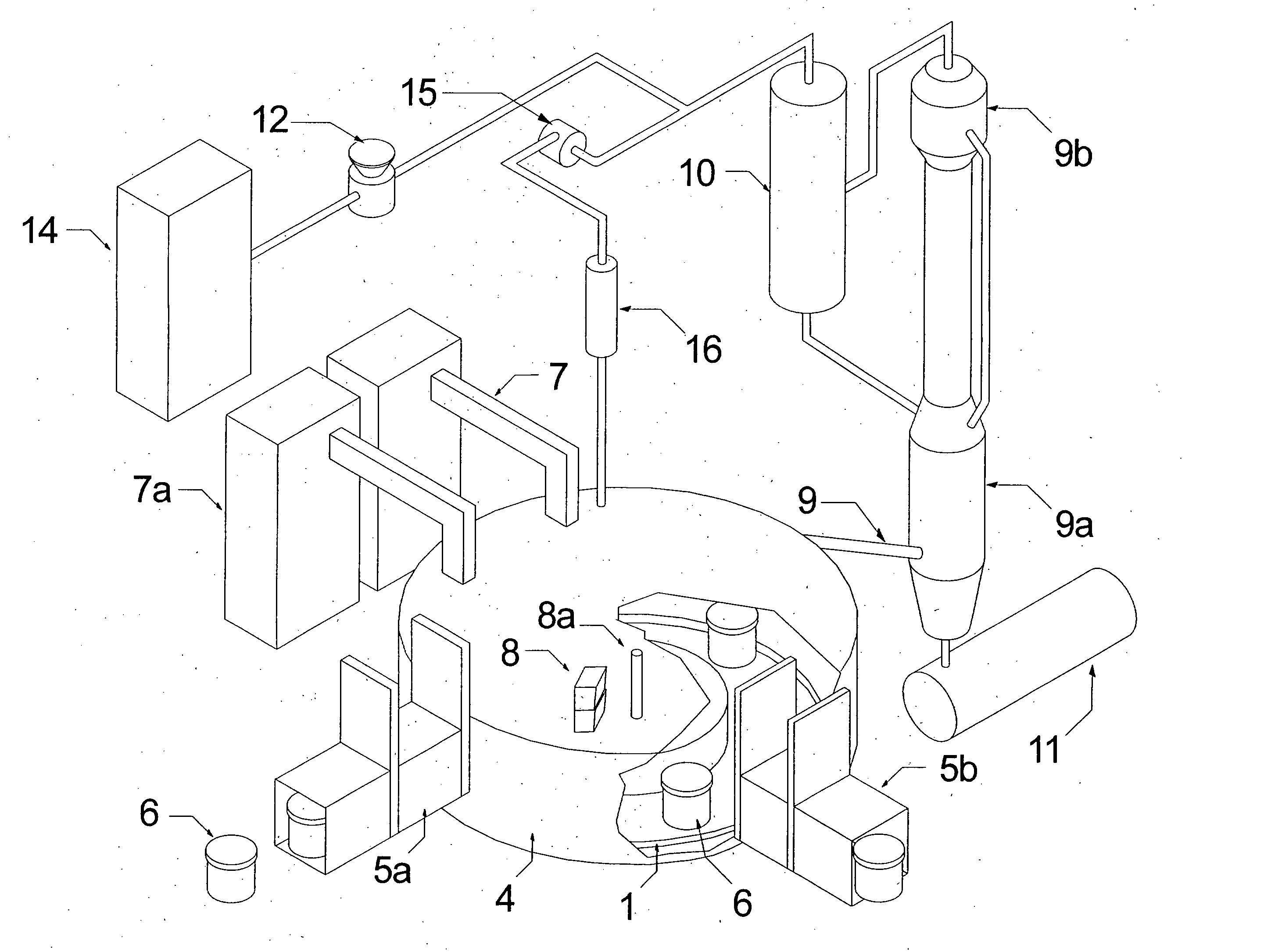
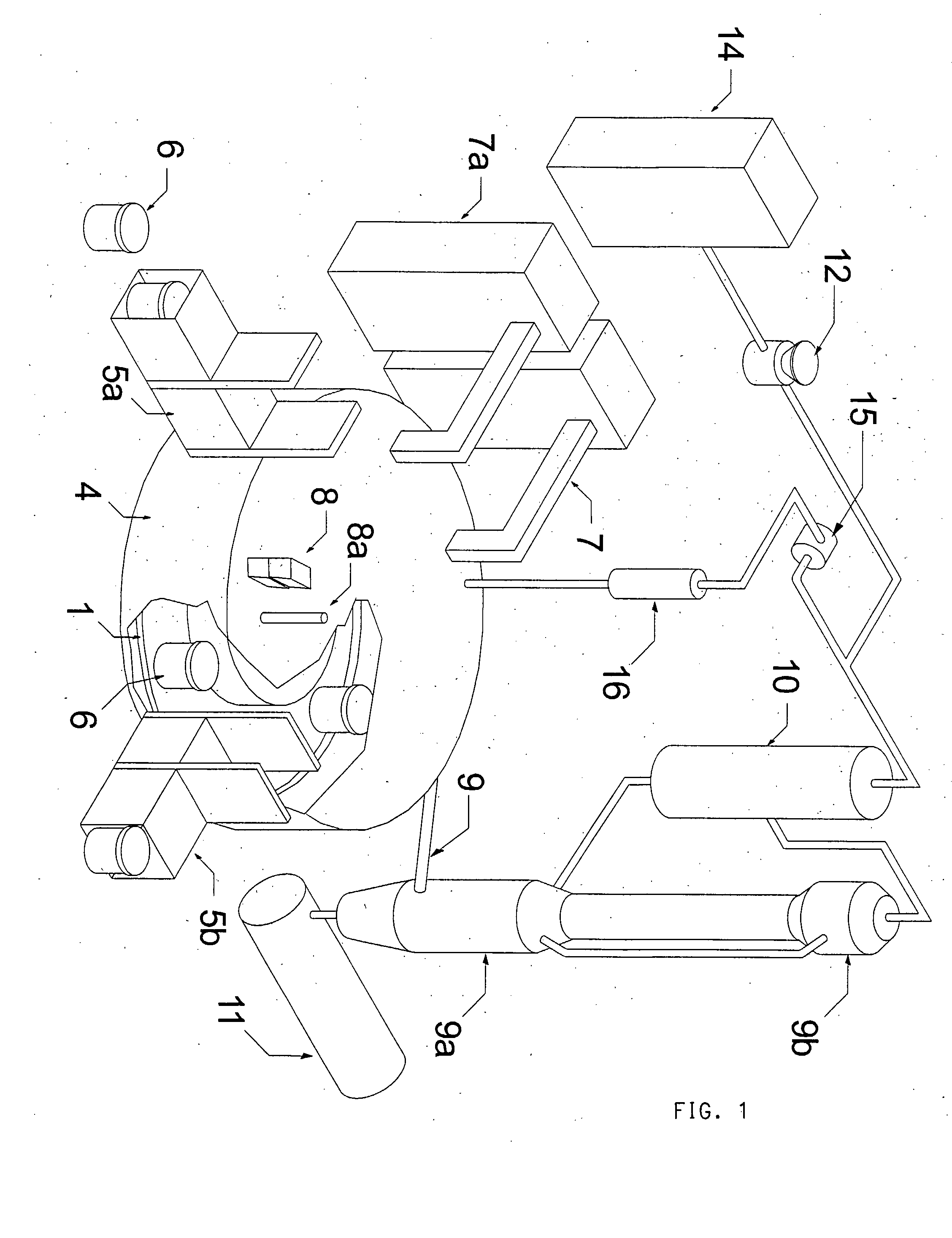
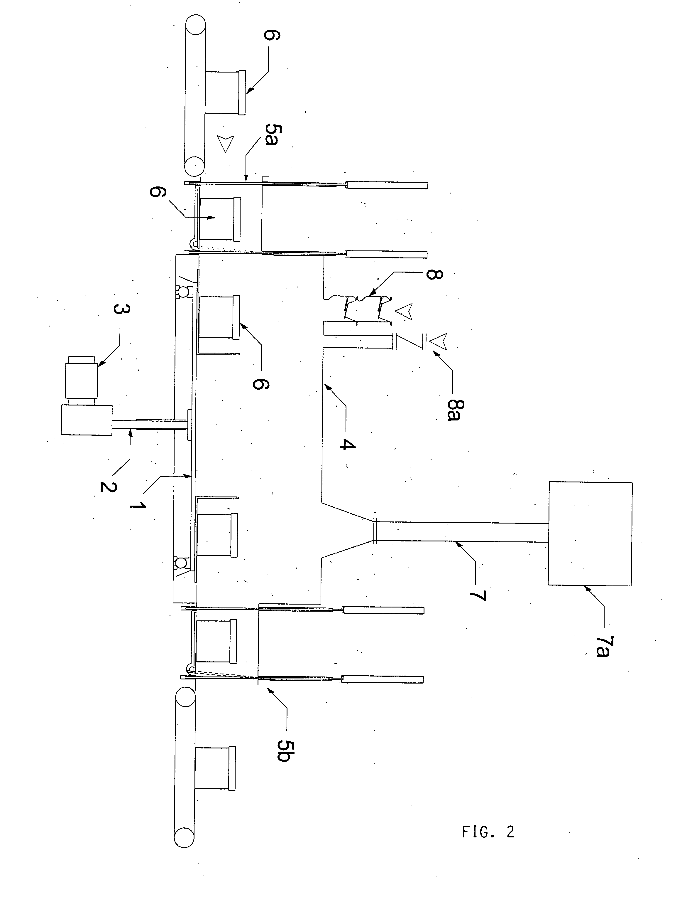
[0061]A carousel 1 is rotatable on a vertical shaft 2 driven by an electric motor 3 (FIG. 2). The carousel is disposed close to the base of a closed airtight cylindrical container 4. Feeding airlock 5a permits the insertion of crucibles 6 into the closed airtight container 4, and discharge airlock 5b permits removal of those crucibles after processing. Ports 7 allow the application of microwave energy from generators 7a to heat material in the crucibles 6 within the closed airtight container 4. Solid additives (e.g. catalysts) may be introduced into the closed airtight container 4 through an airlock 8, and liquid additives may be introduced through a liquid feed device 8a.

[0062]As shown in FIG. 1 (but not in FIG. 2) vent 9 allows the removal of gases generated by the microwaves. Gases pass to a distillation column 9a, a condenser 9b, and to scrubber 10. An oil storage tank 11 receives oil condensed from the distillation column 9a.

[0063]Gas from the top of the scrubber 10 may pass ...


PUM

PropertyMeasurementUnit
decomposition temperatureaaaaaaaaaa
energyaaaaaaaaaa
velocityaaaaaaaaaa

Abstract

Apparatus for the destructive reclamation of materials and energy from municipal wastes and other raw materials through the use of Microwave induced Gasification and Pyrolysis, where the waste or raw material may be circulated once or several times through the process thus enabling the programming of different processes to differing materials and desired end products. The form employed being linear, circulating conveyors or rotating carousels that may carry trays or crucibles, some of which may be equipped with linings that absorb microwaves to enable the early charring of materials that do not initially absorb microwaves and thus will not heat up on their own.

Description

TECHNICAL FIELD OF THE INVENTION[0001]The invention relates to the application of pyrolysis to waste to reclaim matter or energy from that waste.BACKGROUND OF THE INVENTION[0002]The recycling of different materials and the conversion of the energy contents of waste becomes ever more relevant and the target of large scale investments, private as well as public. The procedure used normally is to pre-sort those materials found in the municipal waste which may be recycled. What remains are materials that may be converted into energy through, for example, incineration.[0003]The problem of waste accumulation grows steadily. It is expensive both in terms of collection costs and fees charged, and is particularly unacceptable in terms of the valuable resources that are wasted.[0004]Incineration is a common method for retrieving energy from waste that can not be recycled. The energy is usually converted into heat in the form of hot water or steam that subsequently may replace “nobler” forms o...

Claims


Application Information

Patent Timeline
Patent Type & Authority Applications(United States)
IPC IPC(8): B09B3/00C10B53/00A62D3/00C10B19/00
CPCC10B53/00C10B19/00Y02P20/129B09B3/10
Inventor KASIN, KJELL IVAR
Owner SCHWEITZER
Why Eureka
Try Eureka