

Oriented polymer composite template
a polymer composite material and template technology, applied in the field of oriented polymer composite material production, can solve the problems of weak polymer, subject to transverse cracking or fibrillation, inability to modify, and create surface imperfections
- Summary
- Abstract
- Description
- Claims
- Application Information
AI Technical Summary
Problems solved by technology
Method used
Image

Examples
example 1
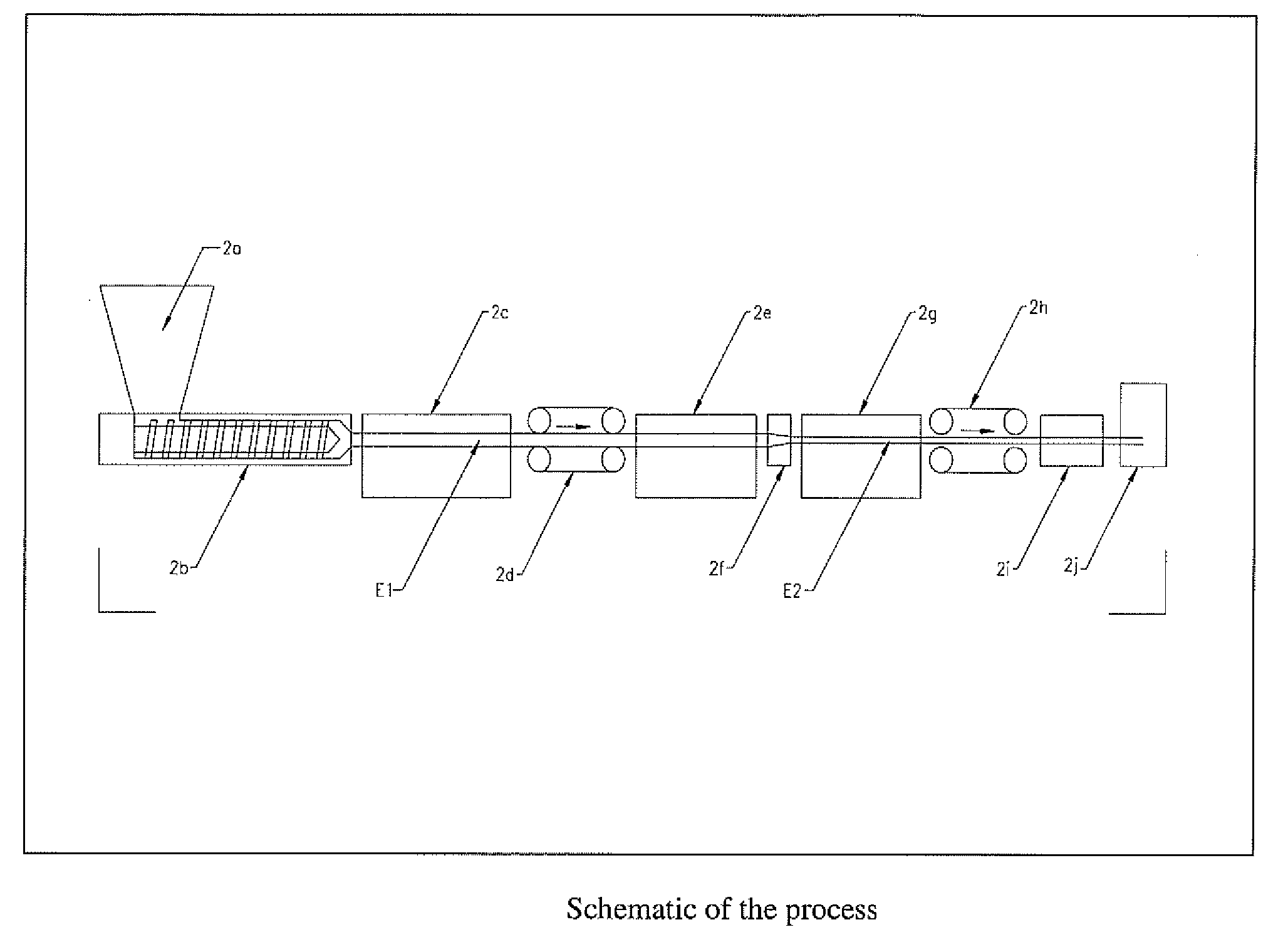
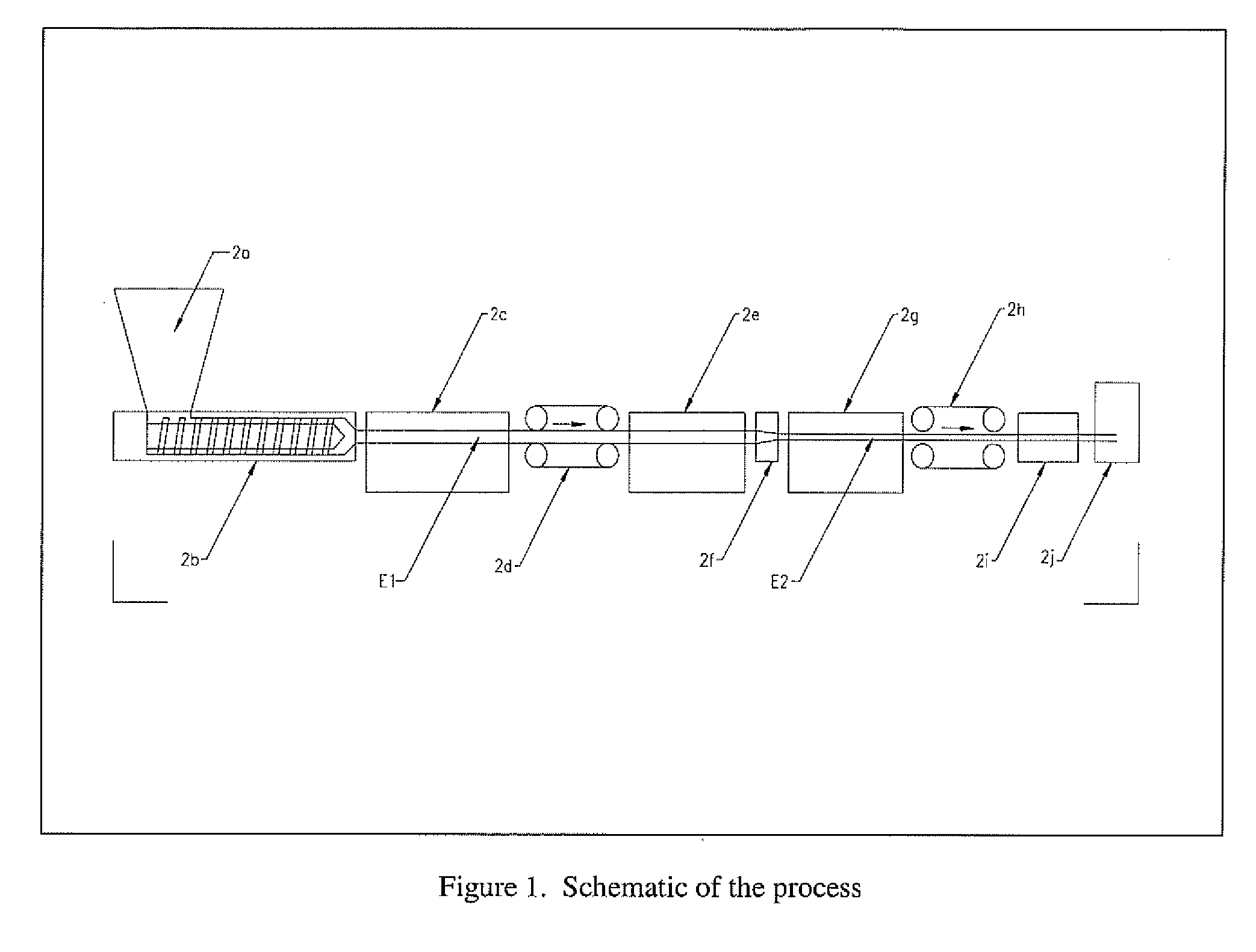
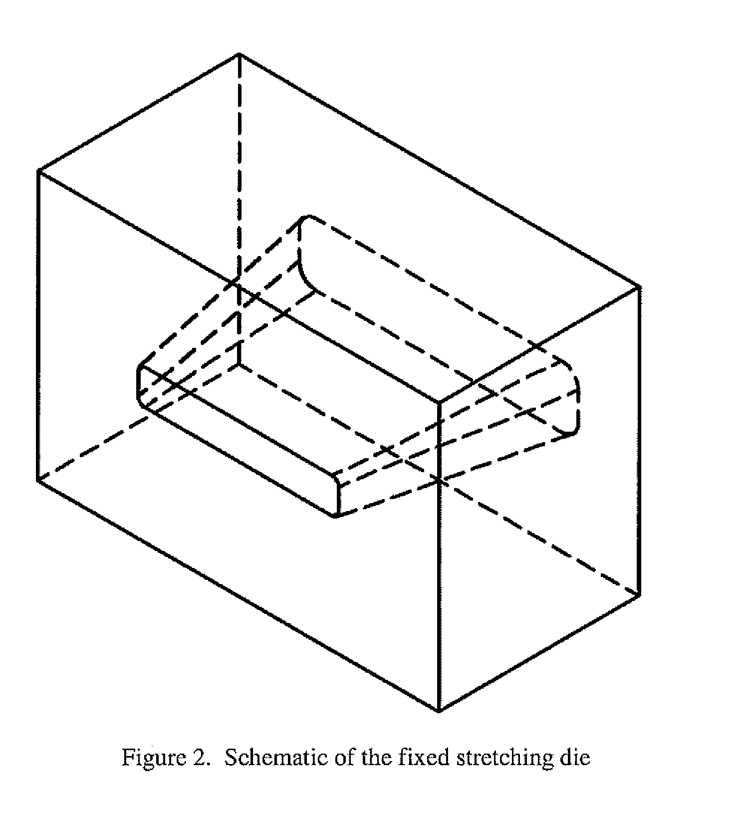
[0087]A mixture of 50 wt % polypropylene and 50 wt % ground calcium carbonate (CaCO3) and process additives were mixed and extruded into a 2″×0.5″ unoriented extrudate, as is common in the art. This extrudate strip was calibrated for size and cooled in a common cooling tank. The extrudate then passed through a standard 36″×3″ belted puller at 1.5 ft / min. The extrudate then passed through a temperature conditioning section such that the surface temperature at the exit of the temperature conditioning section was approximately 265 degrees Fahrenheit as measured with an infrared pyrometer. The extrudate then moved through a plane strain stretching die whose outlet height is adjustable (see FIG. 3). Further, the extrudate passes through a common industry standard cooling tank and into an industry standard 48″×4″ cleated puller and sliding saw.
[0088]By adjusting the outlet dimensions of the stretching die and the speed of the 48″×4″ puller, various products can be produced, as seen in FIG...
example 2
[0092]A mixture of 60 wt % polypropylene, 20% 60# wood flour, and 20 wt % ground calcium carbonate (CaCO3) and process additives were mixed and extruded into a 2″×0.5″ unoriented extrudate, as is common in the art. An example of the ability to use back tension and an adjustable draw die is included for 3 different DTR's (see FIG. 9). During the experiments, conditions were found in which the back tension was so great that drawing occurred in the temperature conditioning area (the terminal stretch ratios for DTR 1.54 and 2.57) and where the part broke during drawing with back tension at DTR 2.81 and broke under stretching with no back tension at a stretch ratio of 10, delineating the envelope of conditions where the technique could be used in this specific composition.
[0093]FIG. 10 shows the change in density with stretch ratio under the various conditions in EXAMPLE 2. In particular, the density reduction of the oriented part compared to the unoriented starting material is illustrat...
example 3
[0094]A mixture of 60 wt % polypropylene, 20% 60# wood flour, and 20 wt % of a ground calcium carbonate (CaCO3) (different from the CaCO3 in Example 2) and process additives were mixed and extruded into a 2″×0.5″ unoriented extrudate in a manner common in the art. Setting the DTR at 1.57 and varying the stretch ratio by setting a difference between puller 1 and puller 2 yielded materials with higher density and higher mechanical properties than the material containing untreated calcium carbonate (Example 2). From Example 2 at similar conditions, there was a density increase of 4.7% due to decreased void formation with the second type of calcium carbonate. Electron micrographs of the structures with void forming fillers and non-void forming fillers are shown in FIGS. 13 and 14, respectively. The electron micrograph in FIG. 13 illustrates the non-bonding of wood particles to polypropylene, and the voids created behind the wood particles as the material is stretched. The electron micro...
PUM
| Property | Measurement | Unit |
|---|---|---|
| Percent by mass | aaaaa | aaaaa |
| Temperature | aaaaa | aaaaa |
| Weight | aaaaa | aaaaa |
Abstract
Description
Claims
Application Information