Method for forming composite components and tool for use therein

a composite component and tool technology, applied in the field of forming composite components and tool for use therein, can solve the problems of difficult to form accurately local changes in geometry in the component at the desired locations in the lengthwise direction, and achieve the effect of accurate formation of local changes in geometry and facilitate the matching of lengthwise expansion

Inactive Publication Date: 2009-01-01
AIRBUS OPERATIONS LTD
View PDF5 Cites 25 Cited by
  • Summary
  • Abstract
  • Description
  • Claims
  • Application Information

AI Technical Summary

Benefits of technology

[0014]This first aspect of the present invention may be advantageous when making long components. In this case, the method of the first aspect of the present invention facilitates the matching of the lengthwise expansion of the intensification tool and the component, therefore enabling the accurate formation of local changes in geometry in t

Problems solved by technology

The applicants have recognised that processes using intensifiers with a high coefficient of thermal expansion in three dimensions suffer from problems when used for long components.
For example, as a result of the intensifier having a high thermal expansion coefficient (

Method used


Image

  • Method for forming composite components and tool for use therein
  • Method for forming composite components and tool for use therein
  • Method for forming composite components and tool for use therein

Examples


Embodiment Construction

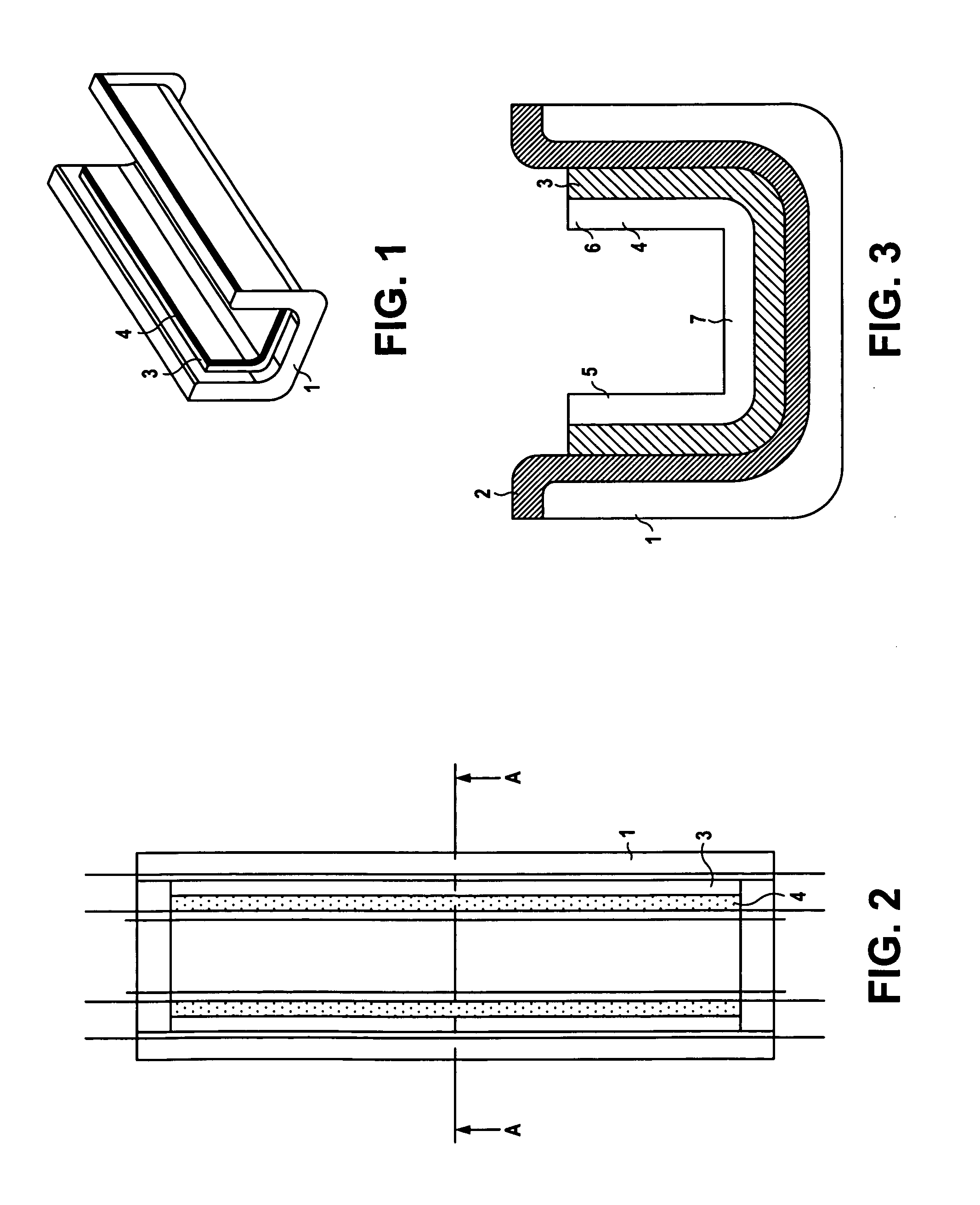
[0064]A known method of making a component is now described with reference to FIGS. 1, 2 and 3. FIGS. 1, 2 and 3 show the spatial relationship between an intensification tool (shown generally by reference numeral 4), the material 3 from which the component is to be made and a mould (shown generally by reference numeral 1) that is used to make a component. The intensification tool 4 is brought into spatial relationship with the mould so as to form a cavity into which material 3 may be provided. Material (for example, in the form of reinforcing fibres dispersed in a matrix-forming precursor) is introduced into the cavity.

[0065]The material 3 is then heated whilst pressure is applied to the material by the intensification tool 4 (due to thermal expansion as described above). The material is heated until it reaches its desired cure temperature and the material is then held at this temperature for a pre-determined period of time (the dwell time) causing the formation of the component, he...


PUM

PropertyMeasurementUnit
Angleaaaaaaaaaa
Lengthaaaaaaaaaa
Coefficient of linear thermal expansionaaaaaaaaaa

Abstract

A method of making an aircraft component is provided, wherein the method comprises the steps of:
    • providing a mould (1) for the receipt of a material (3) from which the aircraft component is to be made providing the mould with said material providing an intensification tool (14) in spaced relationship to the mould and
    • heating the material, tool and mould so that the tool expands and applies pressure to the material and so as to form the component and
    • wherein the linear coefficient of thermal expansion of the tool in a first direction is matched to the coefficient of thermal expansion of the component in the first direction, and the coefficient of thermal expansion of the tool in a second direction is greater than the coefficient of thermal expansion of the component in the second direction, the tool being provided with at least one contacting surface for contacting the material and through which pressure is applied to the material, the expansion of the tool in the second direction causing the at least one contacting surface to contact, and exert pressure on, the material.

Description

TECHNICAL FIELD OF THE INVENTION[0001]The present invention relates to a method suitable for forming composite components and a tool for use in such a method. The method may also be used to form other components using a moulding process.BACKGROUND OF THE INVENTION[0002]Composite components may be manufactured using moulding processes using a mould to form a component during a forming process, in which heat and pressure are typically applied. The mould provides a surface which forms a component surface having a complementary shape to the mould surface. Intensification tools (“intensifiers”) are sometimes used in carbon fibre reinforced plastic component manufacture. Intensifiers enable the surface of the component which is not in contact with the mould tool to be moulded with greater precision. Intensifiers also assist in reducing the bulk volume of the component during the forming process. This debulking removes air from the material to help avoid undesirable voids in the final comp...

Claims


Application Information

Patent Timeline
IPC IPC(8): B28B11/10B29C59/02B29C70/44
CPCB29C70/446B29C37/005
Inventor ASTWOOD, SIMONEVANS, STEVEN
Owner AIRBUS OPERATIONS LTD
Why Eureka
Try Eureka