Calibration circuits and methods for proximity detector

a technology of proximity detector and calibration circuit, which is applied in the field of integrated circuits, can solve the problems of inaccurate output, no output, and degraded calibration threshold, etc., and achieve the effect of improving the output of the proximity detector, avoiding the deformation of the calibration threshold, and improving the accuracy of the calibration threshold

Active Publication Date: 2009-01-01
ALLEGRO MICROSYSTEMS INC
View PDF17 Cites 67 Cited by
  • Summary
  • Abstract
  • Description
  • Claims
  • Application Information

AI Technical Summary

Benefits of technology

[0015]With these particular arrangements, the excursion limits provide a proximity detector and proximity detection method that are less affected by the presence of a signature region in a magnetic field signal.

Problems solved by technology

Immediately upon startup, the threshold may have a value that results in an improper output from the proximity detector.
However, if the signature region is generated near to a time when the proximity detector is attempting a calibration (typically near to a start up time), the calibration of the threshold(s) can be degraded, resulting in an inaccurate output, or no output, from the proximity detector for at least a period of time.

Method used


Image

  • Calibration circuits and methods for proximity detector
  • Calibration circuits and methods for proximity detector
  • Calibration circuits and methods for proximity detector

Examples


Embodiment Construction

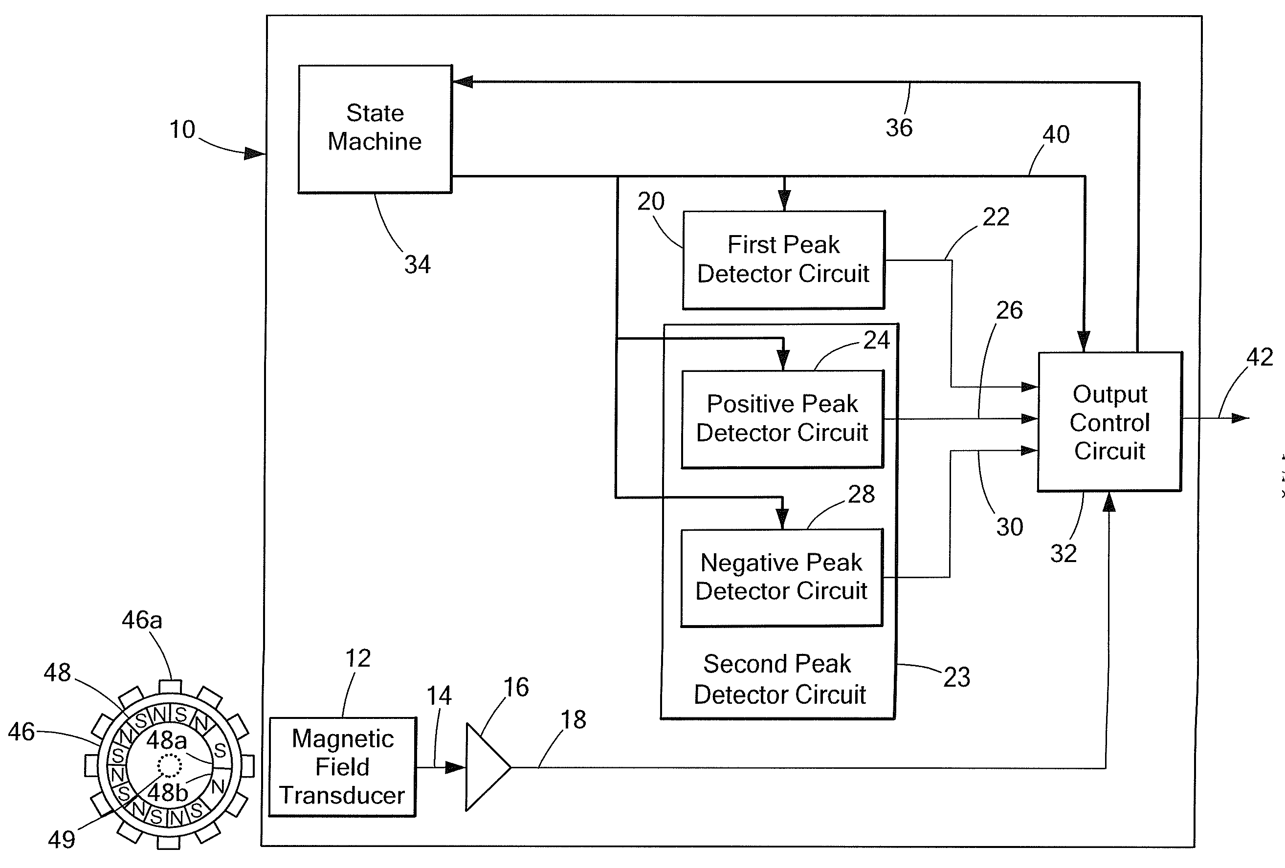
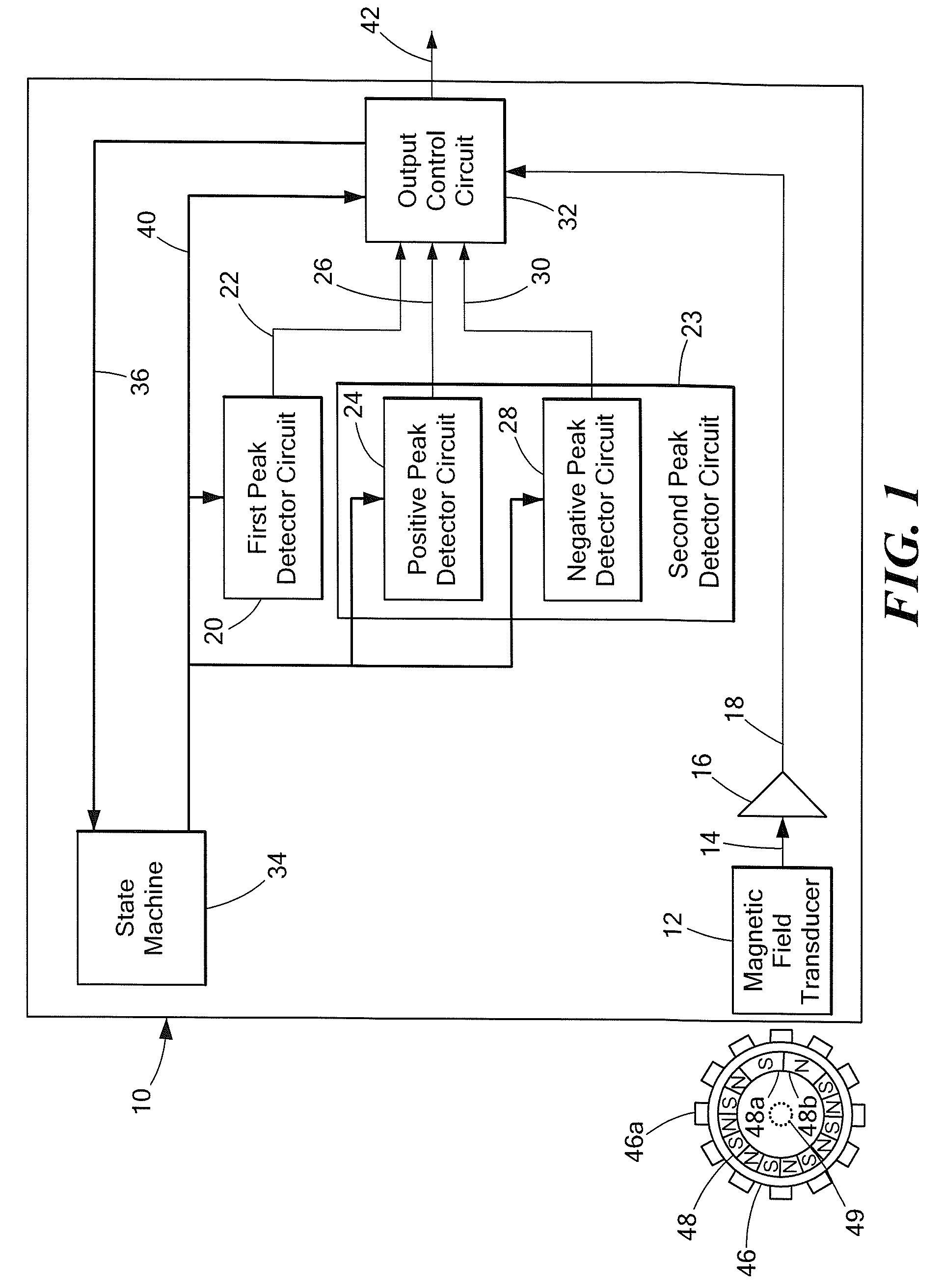
[0026]Before describing the present invention, some introductory concepts and terminology are explained. As used herein, the term “peak detector circuit” is used to describe a circuit that can hold a signal representative of a positive peak or a negative peak (or both) of a magnetic field signal. It should be understood that both a peak-referenced detector and a peak-to-peak percentage detector employ a peak detector circuit of some sort.

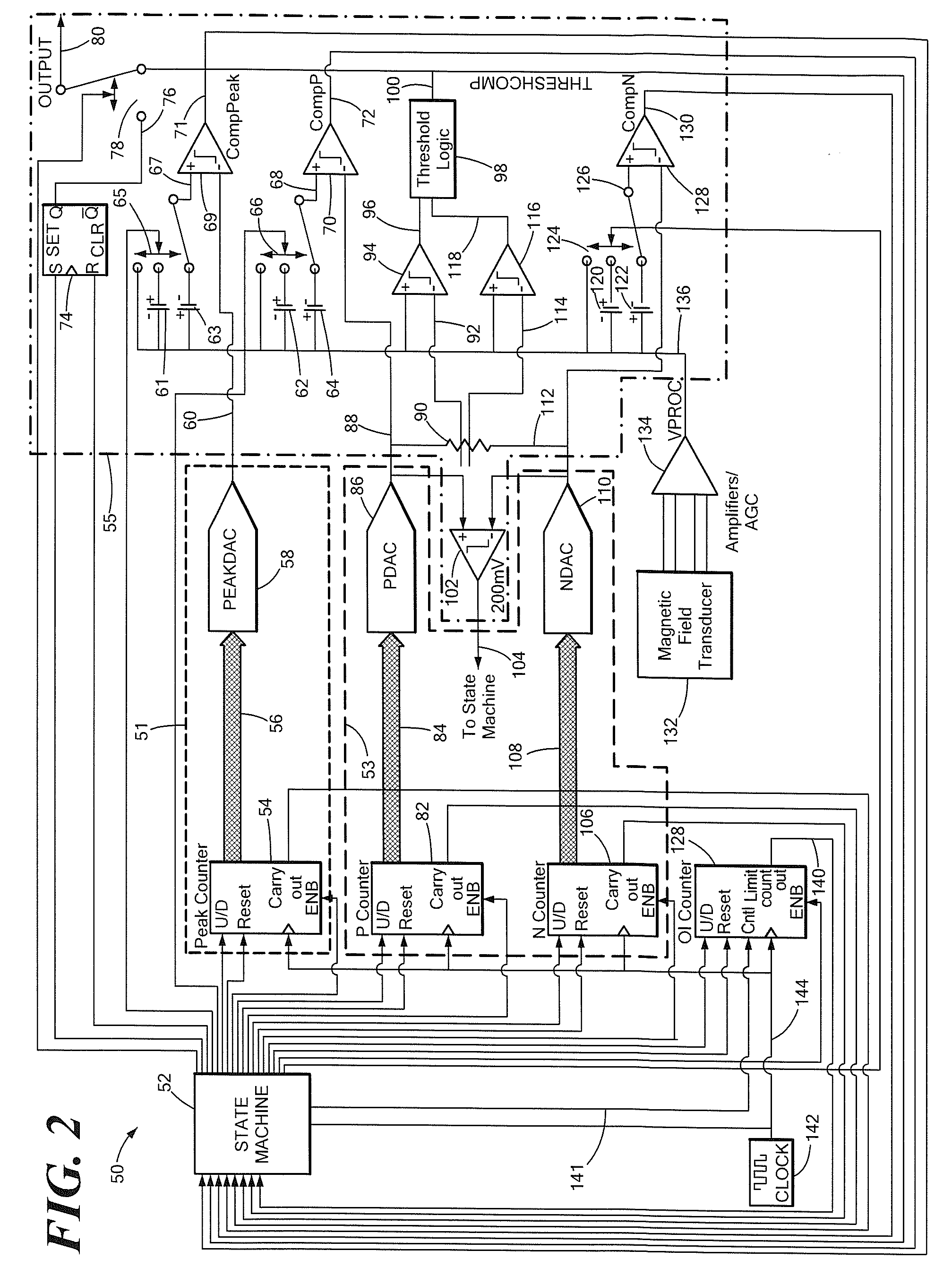
[0027]Operation of a so-called “calibration mode” is described herein. Reference is also made herein to a so-called “running mode,” in particular, a running mode associated with a peak-to-peak percentage detector. Operation of the running mode is described in greater detail in one or more of the above-mentioned patents, notably, U.S. Pat. No. 5,917,320 and U.S. patent application Ser. No. 11 / 333,522, which, along with all of the above-mentioned patents, are incorporated by reference herein in their entirety.

[0028]Referring to FIG. 1, an exemplary in...


PUM


Abstract

A proximity detector employs a first peak detector circuit and a second peak detector circuit, both responsive to a magnetic field signal. The second peak detector circuit includes a positive peak detector circuit and a negative peak detector circuit, each of which have a predetermined excursion limit in an outward direction away from a center voltage of the magnetic field signal so as to be less affected by a large signature region in the magnetic field signal. The proximity detector also includes an output control circuit. The output control circuit is configured to provide an output signal, which, during a determined time period, changes state in response to the first peak detector circuit, and which, after the determined time period, changes state in response to the second peak detector circuit.

Description

CROSS REFERENCE TO RELATED APPLICATIONS[0001]Not Applicable.STATEMENT REGARDING FEDERALLY SPONSORED RESEARCH[0002]Not Applicable.FIELD OF THE INVENTION[0003]This invention relates generally to integrated circuits and, more particularly, to integrated circuits for detecting movement or rotation of a ferrous object or a magnet.BACKGROUND OF THE INVENTION[0004]Proximity detectors for detecting ferrous articles and / or magnetic articles are known. The magnetic field associated with the ferrous article or magnet is detected by a magnetic field transducer, such as a Hall element or a magnetoresistance element, which provides a signal (i.e., a magnetic field signal) proportional to a detected magnetic field. In some arrangements, the magnetic field signal is an electrical signal.[0005]One application for a proximity detector is to detect the approach and retreat of each tooth of a rotating ferrous or soft ferromagnetic gear. In some arrangements, a ring magnet having magnetic regions (perma...

Claims


Application Information

Patent Timeline
Patent Type & Authority Applications(United States)
IPC IPC(8): G01B7/14
CPCG01D5/24452G01D5/2448G01V3/081G01P3/481G01P3/487G01D5/2451G01D18/001
Inventor FERNANDEZ, DEVONEAGEN, JEFFFORREST, GLENN A.DROUIN, MATHEW
Owner ALLEGRO MICROSYSTEMS INC
Why Eureka
Try Eureka