Systems, Methods, and Devices for Commissioning Wireless Sensors

a wireless sensor and wireless technology, applied in the direction of burglar alarm mechanical actuation, burglar alarm by hand-portable object removal, instruments, etc., can solve the problems of overdependence on the optical quality of the label, requirement for line of sight, and the fact that active transponders include batteries

Inactive Publication Date: 2009-01-01
MCALLISTER CLARKE
View PDF4 Cites 47 Cited by
  • Summary
  • Abstract
  • Description
  • Claims
  • Application Information

AI Technical Summary

Problems solved by technology

Active transponders include batteries and, historically, are considered considerably more expensive than passive RFID transponders.
One problem of prior-art systems, such as conventional print labels or barcode systems, includes a requirement for line of sight and an overdependence on the optical quality of the label.
Many factors can render such a label unreadable including printing errors, excess ink, insufficient ink, physical destruction of the markings, obstruction of the markings due to foreign matter, and, in extreme cases, outright deception by placing an altered label over the top of such a print label.
However, current RFID label systems have their own limitations as well.
el. This approach, however, introduces unnecessary waste, cost, and propensities for er
tions. Unneeded printer mechanisms create unnecessary complexities, size, and
weight. In some instances this additional bulk hinders practical mobile appli
cations. The result is that tagging solutions that include printing result in a higher total cost of ownership than a pure RF tag encodin
As with the aforementioned references, this approach adds unnecessary cost and complexity by combining RFID transponders with demand-printed labels.
This patent fails to offer any methods or devices for reading bar code information and using that information to encode an RFID tag.
In particular this patent fails to disclose any methods for conveyance of RFID tags as part of a well-controlled tag encoding process.
The physics of Garber's invention is poorly suited to programming anything other than one tag at a time that is carefully isolated by gr...

Method used


Image

  • Systems, Methods, and Devices for Commissioning Wireless Sensors
  • Systems, Methods, and Devices for Commissioning Wireless Sensors
  • Systems, Methods, and Devices for Commissioning Wireless Sensors

Examples


Embodiment Construction

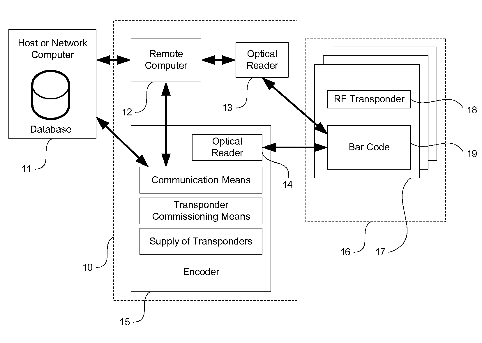
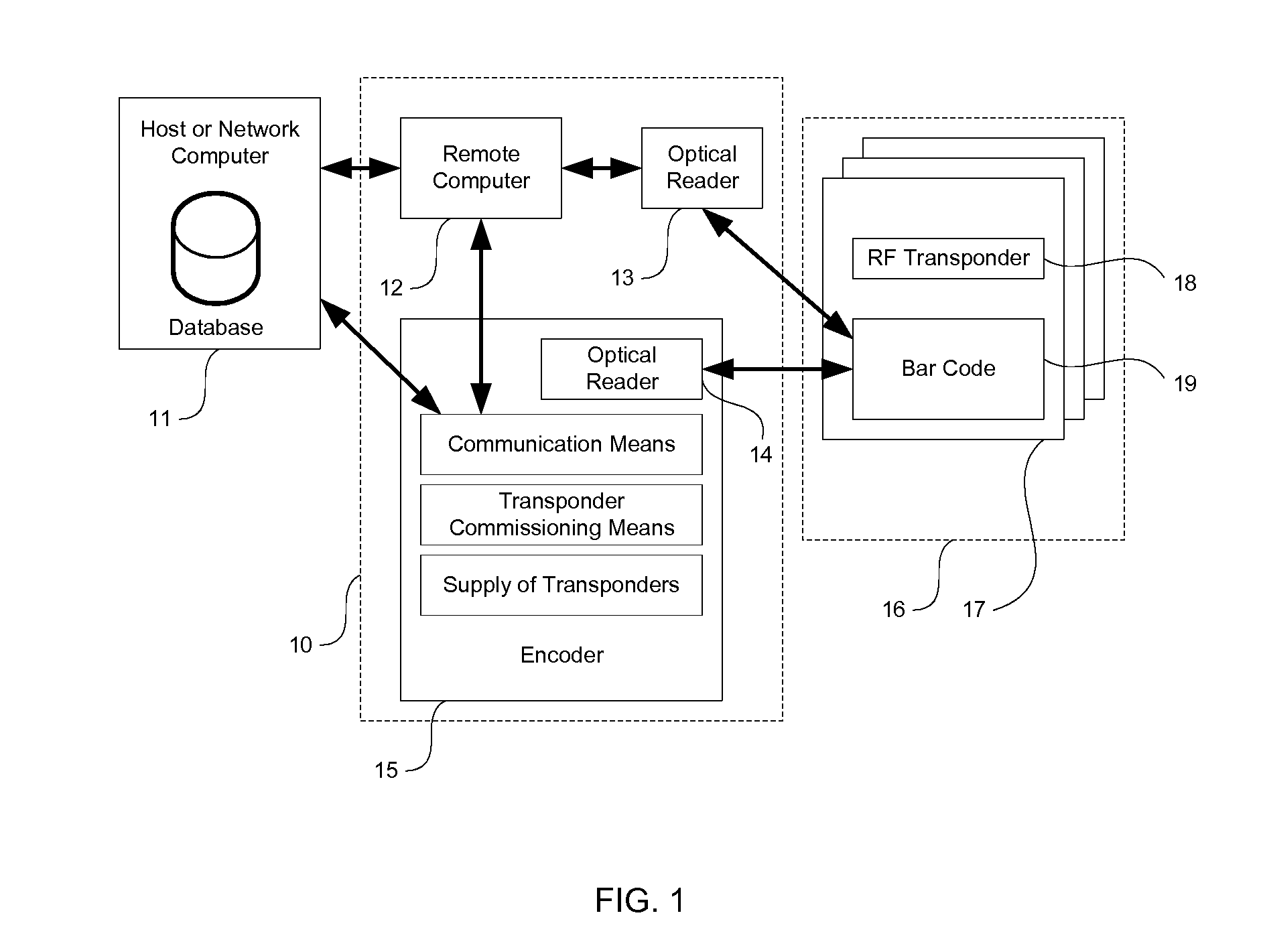
[0059]Making reference to various figures of the drawing, possible embodiments of the present invention are described and those skilled in the art will understand that alternative configurations and combinations of components may be substituted without subtracting from the invention. Also, in some figures certain components are omitted to more clearly illustrate the invention. In some figures similar features share common reference numbers.

[0060]To clarify certain aspects of the present invention, certain preferred embodiments are described in a possible environment—as identification means for containers. In these instances, certain methods make reference to containers such as loaded pallets, paperboard boxes, corrugated cartons, pharmaceutical containers, and conveyable cases, but other containers may be used by these methods. Certain embodiments of the present invention are directed for use with commercial corrugated shipping cartons, tagged pallet-loads of shrink-wrapped cases, c...


PUM


Abstract

In one preferred embodiment the present invention is an encoder for commissioning RFID transponders and includes a housing encasing a motor assembly, a motion and displacement sensor, wireless communication means for transferring instructions and data from and to a remote host, on-board memory, a processor, and an antenna with corresponding mechanism to encode and verify a programmable RFID transponder within a protective enclosure. The present invention further includes novel methods for commissioning RFID transponders, as well as methods for recycling and reusing the protective enclosure.

Description

PRIORITY CLAIM[0001]This present application claims benefit under 35 U.S.C. Section 119(e) of U.S. Provisional Patent Application Ser. No. 60 / 908,194, filed on 27 Mar. 2007, the disclosure of which is expressly incorporated by reference for all purposes.BACKGROUND[0002]The present invention relates to a system, including methods and devices, utilizing wireless sensor devices and RFID (radio-frequency identification) transponders. Specifically, the present invention relates to a system incorporating novel devices and methods that enable point-of-use and on-demand commissioning of RFID transponder-equipped wireless sensors.[0003]Radio-frequency identification (RFID) transponders enable improved identification and tracking of objects by encoding data electronically in a compact tag or label. And, advantageously, the compact tag or label does not need external, optically recognizable or human-readable markings. In fact, using the Gen2 EPC specification, a three-meter read-distance for R...

Claims


Application Information

Patent Timeline
IPC IPC(8): H04Q5/22
CPCG06K1/18G06K19/07749G06K7/0008
Inventor MCALLISTER, CLARKE
Owner MCALLISTER CLARKE
Why Eureka
Try Eureka