Camera system and camera body

a camera system and camera body technology, applied in the field of camera systems and camera bodies, can solve the problems of difficult to make the release time lag short consistent, lose the advantage of vibration compensation, and increase etc., to achieve the effect of reducing the range over which vibration compensation can be performed during photography, and reducing the loss of vibration compensation

Inactive Publication Date: 2009-01-01
NIKON CORP
View PDF7 Cites 29 Cited by
  • Summary
  • Abstract
  • Description
  • Claims
  • Application Information

AI Technical Summary

Benefits of technology

[0009]Furthermore, with this type of camera endowed with a prior art vibration compensation function, during photographic operation in which full pressing of the release button is performed, for a short time the compensation lens is centered at the approximately central position within its range of movement, and then drive control of the compensation lens corresponding to vibration is performed from this approximately central position at which the lens has been centered—in other words, vibration compensation is started—and thereafter photographic operation starts. By doing this, deterioration of the optical performance of the photographic optical system is suppressed as much as possible by centering the compensation lens in its approximately central position. Moreover, by performing centering at the time of photographic operation, the range over which vibration compensation can be performed during photography is made wider, and thus the vibration compensation is made to function for higher levels of vibrations.
[0010]However, if the compensation lens is centered directly before the operation of photography is started, then a delay occurs during the time period until photography is started, and the release time lag becomes longer, and this is a deficiency. Moreover, it is difficult for making the release time lag short to be consistent with handling larger amount of camera vibration by performing extension of the optical performance sufficiently by centering the compensation lens before photography under the sacrificing the release time lag.
[0011]A camera system according to the present invention comprises a vibration compensation unit that comprises at least one of a vibration compensation optical system that makes an optical axis variable, and an image-capturing unit that can be shifted, and that compensates image vibration upon an image surface occurring due to vibration of a camera, a drive unit that drives the vibration compensation unit, a detection unit that detects vibration of the camera, a position detection unit that detects the position of the vibration compensation unit, a target position determination unit that determines a target position for the vibration compensation unit according to vibration of the camera detected by the detection unit, a calculation unit that calculates a drive amount for the drive unit based upon the target position and the position detected by the position detection unit, a range of movement limitation unit that limits the position of the vibration compensation unit within a certain range of movement, a range setting unit that sets a movement permitted range that is a range within the range of movement in which the vibration compensation unit can be positioned by being driven by the drive unit during vibration compensation, and a centering unit that controls the drive unit after photography based upon issue of a photographic command by an operator has ended so that the vibration compensation unit is centered in the approximate center of the movement permitted range.
[0012]It is desirable that the camera system described above further comprises a

Problems solved by technology

If the shutter is released in the state in which the compensation lens is shifted to one corner of its range of movement, then it becomes impossible to shift the compensation lens further in that direction, and there is a fear that sometimes the advantageous effects of vibration compensation may be lost.
However, if the compensation lens is centered directly before the operation of photography is started, then a del

Method used


Image

  • Camera system and camera body
  • Camera system and camera body
  • Camera system and camera body

Examples


first embodiment

The First Embodiment

1-1 Explanation of the Overall Structure

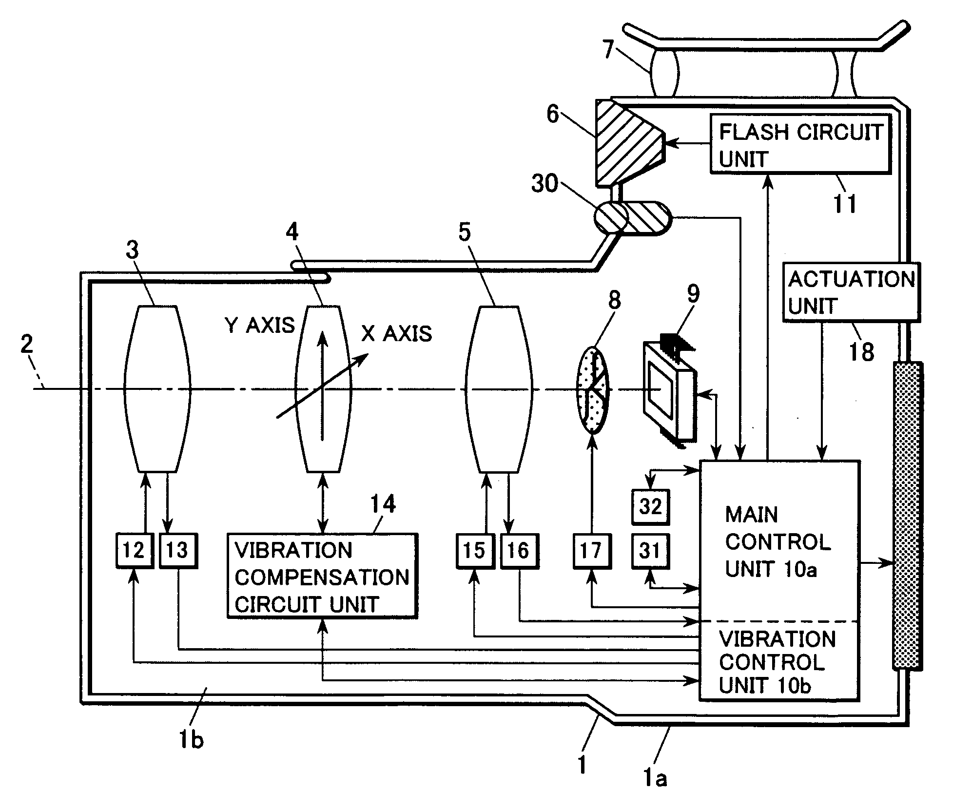
[0053]FIG. 1 is a block diagram showing a camera that is equipped with a vibration compensation device according to the present invention. Here, the concrete example given is a digital still camera. This camera 1 includes a zoom lens 3, a compensation lens 4, a focusing lens 5, a flash unit 6, an optical viewfinder 7, a shutter 8, an image sensor 9, a control unit 10, a flash circuit unit 11, a zoom lens drive unit 12, a zoom lens position detection unit 13, a vibration compensation circuit unit 14, a focusing lens drive unit 15, a focusing lens position detection unit 16, a shutter drive unit 17, an actuation unit 18, an external liquid crystal monitor 19, a sound gathering unit 30, a non-volatile storage medium 31, and an actuation sound generation unit 32.

[0054]The control unit 10 consists of a one chip micro computer and so on, and undertakes overall control of this camera 1. This control unit 10, functionally, is divid...

second embodiment

The Second Embodiment

[0305]In the first embodiment described above, it was arranged to cancel out vibration acting upon the image sensor 9 by driving the compensation lens 4, that constitutes one portion of the photographic optical system, to shift in some direction in a plane orthogonal to the photographic optical axis 2, according to the camera vibration as obtained by the vibration gyros 200a and 200b; but, with regard to the method for image vibration compensation, the system is not to be considered as being limited to this type of structure. FIG. 19 is a block diagram showing a second embodiment of a camera according to the present invention. With the camera shown in FIG. 19, for an image vibration amount that is generated by the photographic optical axis 2 changing due to camera vibration, it is arranged to perform image vibration compensation by shifting the image sensor 9 itself. It should be understood that, in FIG. 9, the same numbers are appended to portions of the struct...

third embodiment

The Third Embodiment

[0309]Furthermore, the camera according to the present invention is not limited to being a digital still camera as described above, in particular to being a compact digital still camera; the present invention could also be applied to a silver halide film camera, or to a single lens reflex camera. FIG. 20 is a figure showing an example in which the present invention has been applied to a digital single lens reflex camera system. The camera 701 shown in FIG. 20 includes a body portion 701a and a lens portion 701b that is made so as to be removable therefrom.

[0310]The relationship between the digital single lens reflex camera system shown in FIG. 20 and the previously described compact digital still camera shown in FIG. 1 (the camera 1) is as follows. That is, elements of the camera 701 shown in FIG. 20 correspond to elements of the camera 1 shown in FIG. 1 in the following manner: a body portion 701a to the body 1a; a lens portion 701b to the lens-barrel 1b; a phot...


PUM


Abstract

This camera system includes: a vibration compensation unit including a vibration compensation optical system and an image-capturing unit; a drive unit that drives the vibration compensation unit; a detection unit that detects vibration; a position detection unit that detects the position of the vibration compensation unit; a target position determination unit that determines a target position for the vibration compensation unit according to the vibration of the camera; a calculation unit that calculates a drive amount for the drive unit; a range of movement limitation unit that limits the position of the vibration compensation unit within a range; a range setting unit that sets a movement permitted range that is within the range in which the vibration compensation unit can be positioned; and a centering unit that controls the drive unit so that the vibration compensation unit is centered in the center of the movement permitted range.

Description

INCORPORATION BY REFERENCE[0001]The disclosures of the following priority applications are herein incorporated by reference:[0002]Japanese Patent Application No. 2007-036062, filed Feb. 16, 2007; and[0003]Japanese Patent Application No. 2007-036156, filed Feb. 16, 2007.BACKGROUND OF THE INVENTION[0004]1. Technical Field[0005]The present invention relates to a camera system and a camera body that can prevent image vibration that originates in camera vibration and the like.[0006]2. Description of Related Art[0007]In Japanese Laid-Open Patent Publication 2001-209084, there is disclosed a vibration compensation device that detects an amount of vibration based upon the angular velocity with which a camera vibrates, or upon the vibration of the image, and that compensates vibration of an image capture surface or of a film surface by driving a vibration compensation lens according to this amount of vibration that has been detected. With this type of vibration compensation device, the vibra...

Claims


Application Information

Patent Timeline
IPC IPC(8): G03B17/00
CPCH04N5/23248H04N5/23287H04N5/23261H04N5/23258H04N23/68H04N23/6815H04N23/6812H04N23/687G03B5/06
Inventor OHISHI, SUEYUKI
Owner NIKON CORP
Why Eureka
Try Eureka