Multi-Speed Drill and Chuck Assembly

a multi-speed, chuck technology, applied in boring/drilling equipment, turning equipment, sleeve/socket joints, etc., can solve the problems of not contributing to the overall functionality of the drill bit and the drill bit being harder to handl

Active Publication Date: 2009-01-01
TECHTRONIC POWER TOOLS TECHNOLOGY LTD
View PDF99 Cites 26 Cited by
  • Summary
  • Abstract
  • Description
  • Claims
  • Application Information

AI Technical Summary

Benefits of technology

[0005]The present invention includes a tool with a chuck assembly that includes a chuck body having an axial forward end and an axial rearward end, a thrust ledge extending radially outward from the chuck body; and a support bearing having an inner periphery mounted to the chuck body and having an outer periphery mounted to a housing of the tool, wherein jaws extending axially rearward can extend into a cavity defined within the housing and located axially rearward of the support bearing. In certain aspects of the invention, the tool can include a clutch mechanism. In other aspects of the invention, the tool can include a spindle lock mechanism that, when actuated, prevents the chuck body from rotating with respect to the housing. In other aspects of the present invention, the tool can include a clutch override mechanism that is operable in any setting of the clutch mechanism.
[0006]The tool of the present invention also includes a speed change mechanism so that the tool operates in more than one speed. The speed change mechanism includes a gearbox housing that cooperates with a ring gear, which is axially translatable with respect to the gearbox housing such that in a first position, the ring gear is rotationally fixed with respect to the gearbox housing and in a second position; the ring gear is free to rotate with respect to the gearbox housing. The ring gear selectively cooperates with a sun gear that drives planet gears meshed with teeth on the ring gear so that the output speed varies from a low speed to a high speed.

Problems solved by technology

To accommodate the axial travel of the jaws, it has been known to make the chuck fairly long, which may make the drill harder to handle, while not contributing to the overall functionality of the drill.

Method used


Image

  • Multi-Speed Drill and Chuck Assembly
  • Multi-Speed Drill and Chuck Assembly
  • Multi-Speed Drill and Chuck Assembly

Examples


Embodiment Construction

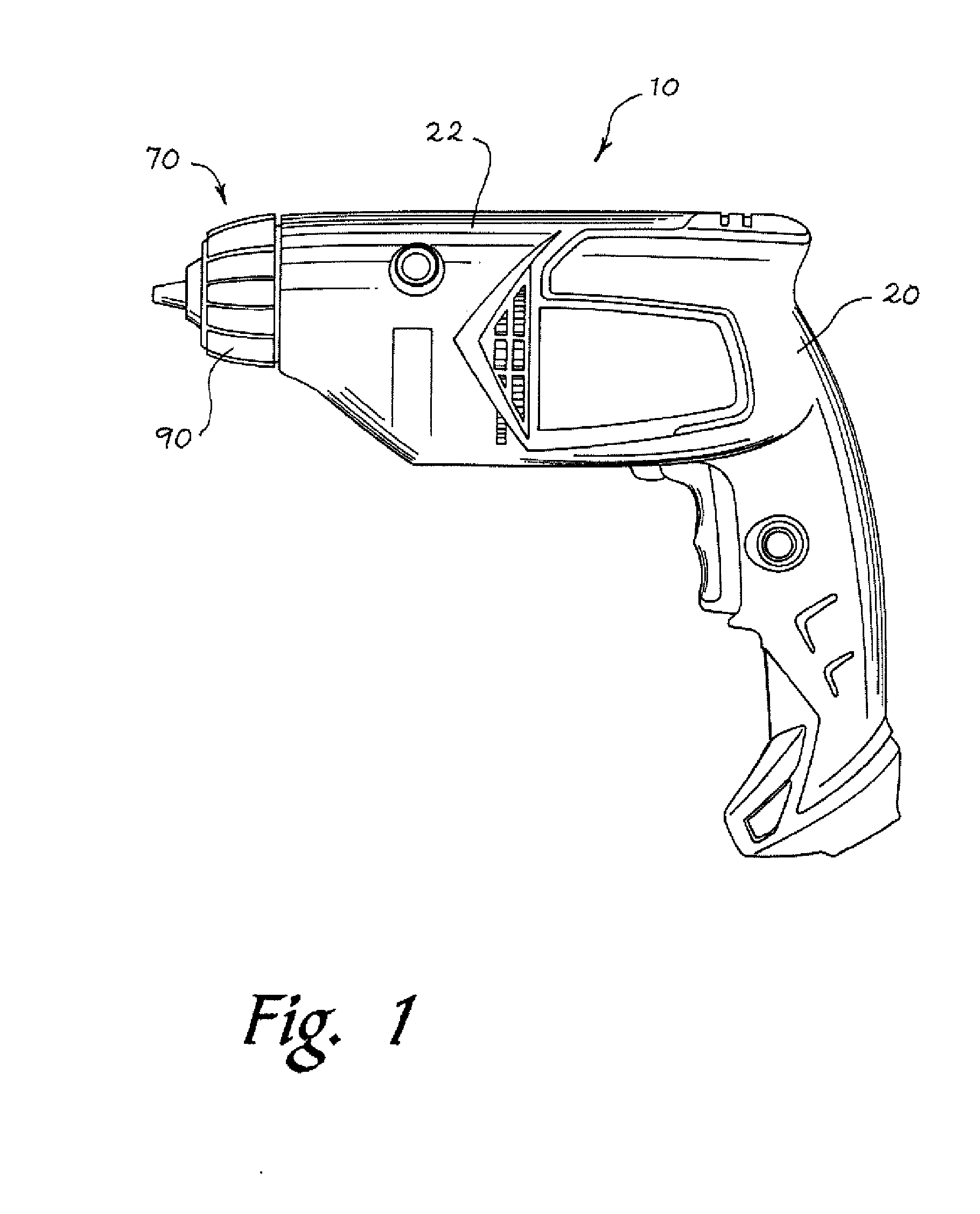
[0036]Turning now to FIG. 1, a tool 10 utilizing the chuck assembly 70 according to the present invention is shown. The tool 10 has a housing 20 generally formed in two parts 22, 24 that are joined to each to form an enclosure for the several parts of the tool 10. The tool 10 shown in FIG. 1 is a hand held drill and is powered by an electrical cord (not shown). One of skill in the art will understand that the chuck assembly 70 of the present invention can be used with a number of different tools but for ease of description, it will be described in connection with a drill. For example, the tool could be a screwdriver, a grinder, or a router, etc. The tool 10 is typically driven by a motor 30 that is powered from an electrical source that can include a hard wire, batteries, or both. Such tools and motors are conventional and therefore a further discussion is not warranted or necessary.

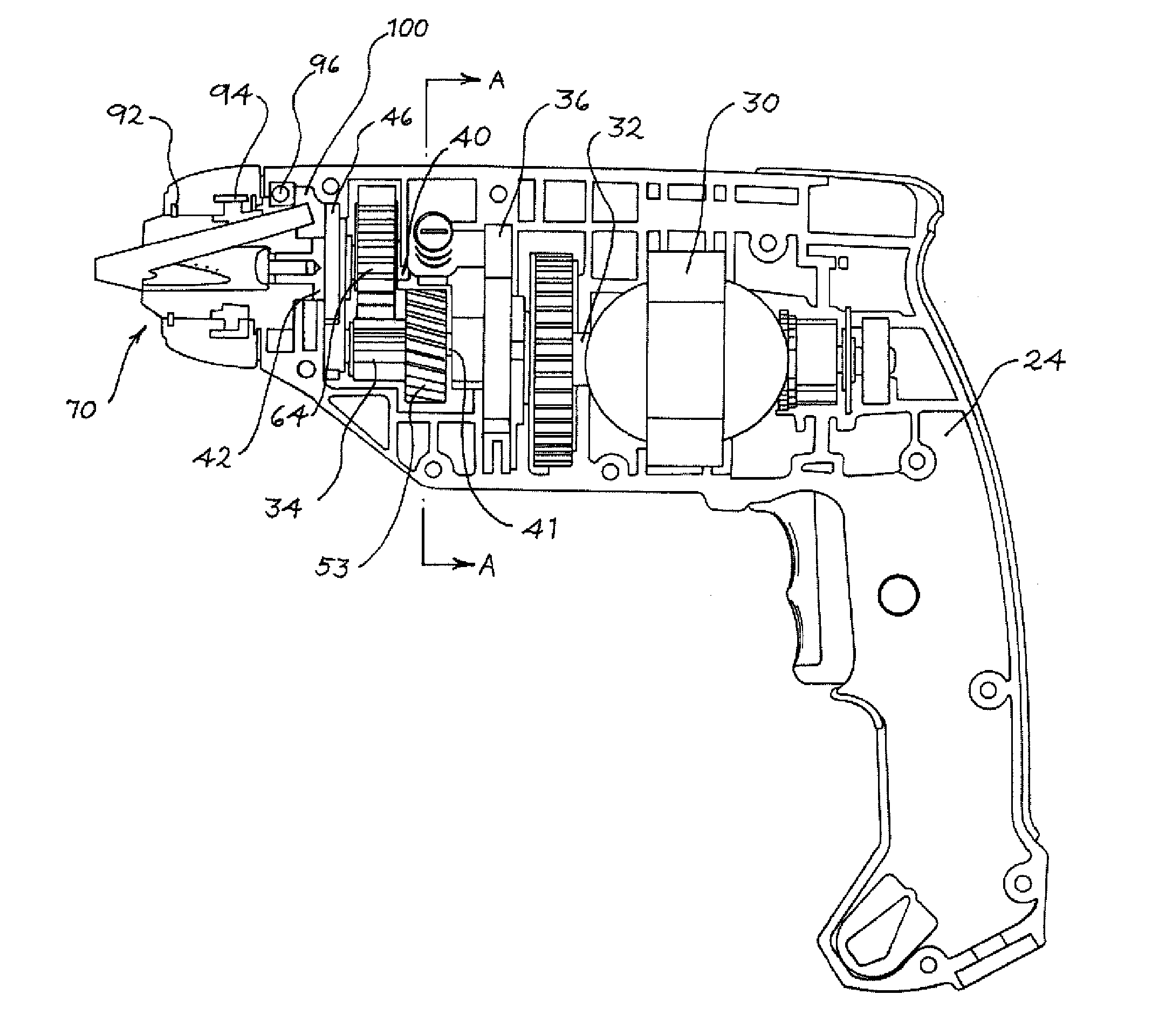
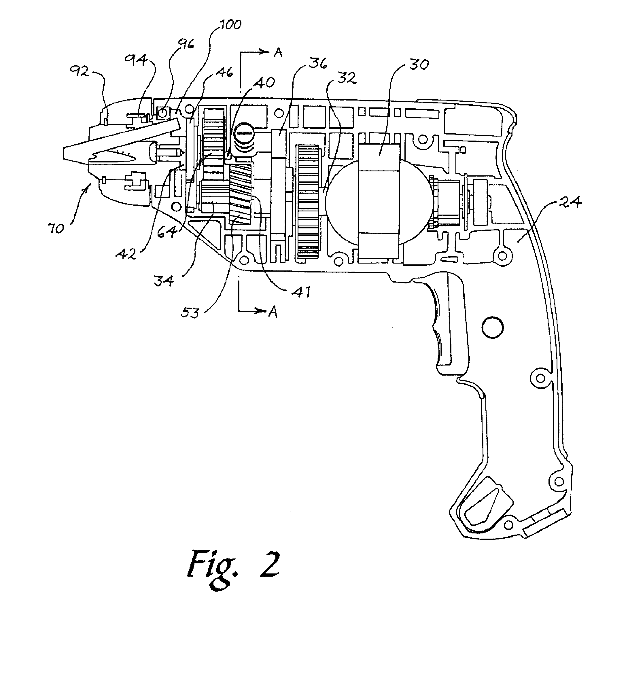
[0037]FIG. 2 shows a cross sectional view of the tool 10 of FIG. 1. It is understood that the half of...


PUM

PropertyMeasurementUnit
speedaaaaaaaaaa
rotationaaaaaaaaaa
torqueaaaaaaaaaa

Abstract

A chuck assembly configured to provide a shorter longitudinal profile. The chuck assembly includes a chuck body with a support bearing mounted to a rear portion of the chuck body and mounted to a portion of a housing such that a cavity is defined axially rearward of the support bearing and is configured to receive the jaws when the rear portion of the jaws extend axially rearward. The chuck assembly can be incorporated into a tool driven by a motor. In some aspects, the tool may include a speed change mechanism, a torque adjustment mechanism, or both.

Description

[0001]This application claims priority to and is a continuation-in-part of U.S. application Ser. No. 11 / 768,509 filed Jun. 26, 2007, the entire contents of which are incorporated herein by reference.FIELD OF THE INVENTION[0002]The present invention relates to a drill and, in particular a drill having a compact chuck assembly. The present invention also relates to a drill having a compact chuck assembly that is operable in more than a single speed.BACKGROUND OF THE INVENTION[0003]Typically, a drill has a chuck assembly that includes jaws that are displaced in passages between axially front and radially closely spaced positions and axially back and radially widely spaced positions. To accommodate the axial travel of the jaws, it has been known to make the chuck fairly long, which may make the drill harder to handle, while not contributing to the overall functionality of the drill.[0004]The present invention provides a chuck assembly that allows the drill and the chuck assembly to be s...

Claims


Application Information

Patent Timeline
Patent Type & Authority Applications(United States)
IPC IPC(8): B23B31/10B23B39/04
CPCB23B31/123B23B31/1238B23B45/008B25B21/00Y10T408/165Y10S279/902Y10T408/953Y10T408/65Y10T279/17632B25B23/141
Inventor MOK, KWOK TINGLAI, KOK VUI
Owner TECHTRONIC POWER TOOLS TECHNOLOGY LTD
Why Eureka
Try Eureka