Fuel cell stack having multiple parallel fuel cells

a fuel cell and stack technology, applied in the field of fuel cell stacks, can solve the problems of increasing the proportion of system volume required for manifolding of inlet and return gases, increasing the cost and size of the cell per unit area of electric generating capacity, and increasing the resistance losses at the cell-to-cell junction

Inactive Publication Date: 2009-01-01
DELPHI TECH INC
View PDF4 Cites 9 Cited by
  • Summary
  • Abstract
  • Description
  • Claims
  • Application Information

AI Technical Summary

Problems solved by technology

Also, the resistive losses at the cell-to-cell junctures increase with each connection, and the proportion of system volume required for manifolding of the inlet and return gases increases.
On the other hand, increasing the cell active area to increase the stack amperage by increasing the areal extent of each cell presents many challenges.
The cell is a planar ceramic structure, so as the size increases the thickness must also increase to preserve the same level of mechanical strength (that is, resistance to breakage) which significantly increases the cost and size (volume) of the cell per unit area of electric generating capacity.
In addition, the manufacturing defect rate is determined by the number of defects per cell, not per unit area, so as the area of a cell increases the number of defects per cell will increase, which adversely affects the overall manufacturing rejection rate in both cell manufacturing and stack manufacturing.
Alternatively, the width or length may be increased while maintaining the same length or width, but this departure from a prior art near-square cell shape makes firing of the ceramic cell very difficult while maintaining acceptable flatness and uniform shrinkage.

Method used


Image

  • Fuel cell stack having multiple parallel fuel cells
  • Fuel cell stack having multiple parallel fuel cells
  • Fuel cell stack having multiple parallel fuel cells

Examples


Embodiment Construction

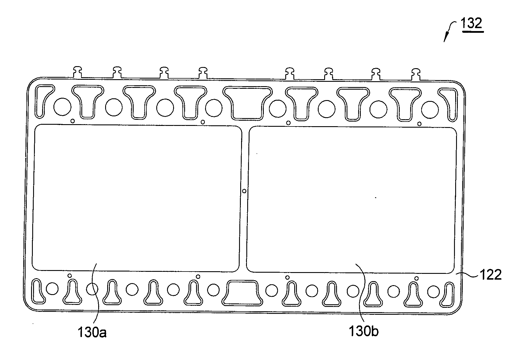
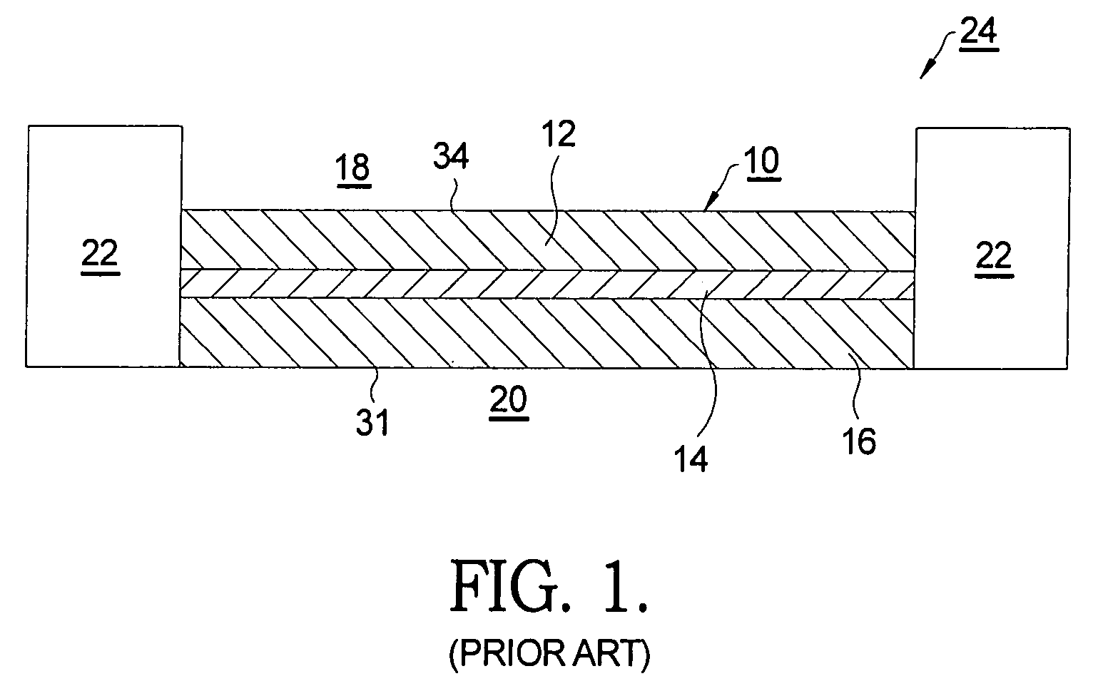
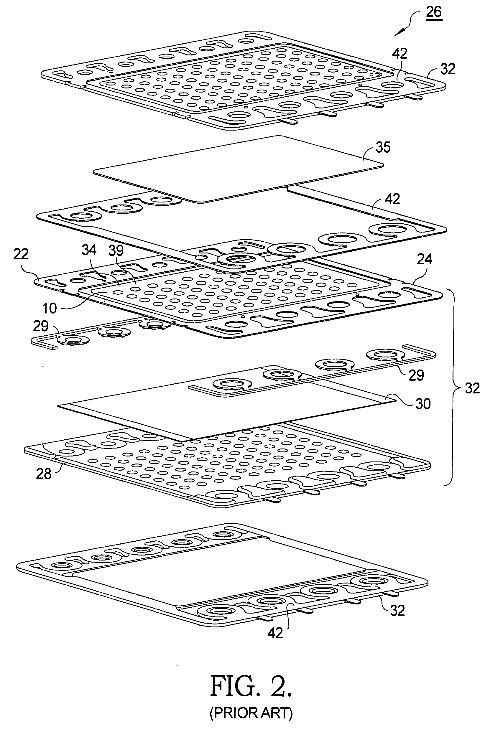
[0024]Referring to FIGS. 1 and 2, an exemplary prior art SOFC fuel cell module 10 comprises a cathode layer 12, an electrolyte layer 14 formed of a solid oxide and bonded to the cathode layer 12, and an anode layer 16 bonded to the electrolyte layer 14 on a side opposite from the cathode layer. Air 18 is passed over the surface 34 of the cathode layer 12, and oxygen from the air migrates through the electrolyte layer 14 and reacts in the anode layer 16 with hydrogen anode gas 20 being passed over the anode surface 31 to form water, thereby creating an electrical potential between the anode and the cathode of about 1 volt. Each individual fuel cell module 10 is mounted, for handling, protection, and assembly into a stack, within a metal frame 22 referred to in the art as a “picture frame”, to form a “cell-picture frame assembly”24.

[0025]To facilitate formation of a prior art stack 26 of individual fuel cells connected in series wherein the voltage formed is a function of the number o...


PUM

PropertyMeasurementUnit
operating voltagesaaaaaaaaaa
electrical potentialaaaaaaaaaa
voltageaaaaaaaaaa

Abstract

A fuel cell stack comprising a plurality of serially-connected fuel cell stages, each stage comprising a plurality of fuel cells arranged electrically in parallel such that each stage has the voltage drop of a single fuel cell but current output defined by the total cell area. The assembled stack thus comprises essentially a plurality of internal fuel cell stacks arranged in parallel, each stack having the same voltage, and the stack currents being additive. The total voltage is the same as for a prior art stack of the same number of stages, but the current and hence the power output is multiplied over that of a single-cell stack by the number of internal fuel cell stacks. Preferably, each stage is a cassette including a plurality of windows for receiving the individual fuel cell units; a plurality of anode and cathode interconnects; and a single separator plate.

Description

RELATIONSHIP TO GOVERNMENT CONTRACTS[0001]The present invention was supported in part by a US Government Contract, No. DE-FC26-02NT41246. The United States Government may have rights in the present invention.TECHNICAL FIELD[0002]The present invention relates to fuel cell stacks; more particularly, to a fuel cell stack having multiple parallel fuel cells; and most particularly to a solid oxide fuel cell stack comprising a plurality of fuel cell cassettes arranged in series electric flow wherein each cassette includes at least two fuel cells arranged in parallel electric flow.BACKGROUND OF THE INVENTION[0003]In practical fuel cell systems, the output of a single fuel cell is typically less than one volt, so connecting multiple cells in series is required to achieve useful operating voltages. Typically, a plurality of fuel cell stages, each stage comprising a single fuel cell unit, are mechanically stacked up in a “stack” and are electrically connected in series electric flow from the ...

Claims


Application Information

Patent Timeline
Patent Type & Authority Applications(United States)
IPC IPC(8): H01M2/00
CPCH01M8/0247H01M8/0273H01M8/2425Y02E60/525H01M2008/1293Y02E60/50H01M8/249H01M8/2483H01M8/2428H01M8/242
Inventor HALTINER, JR., KARL J.MUKERJEE, SUBHASISH
Owner DELPHI TECH INC
Why Eureka
Try Eureka