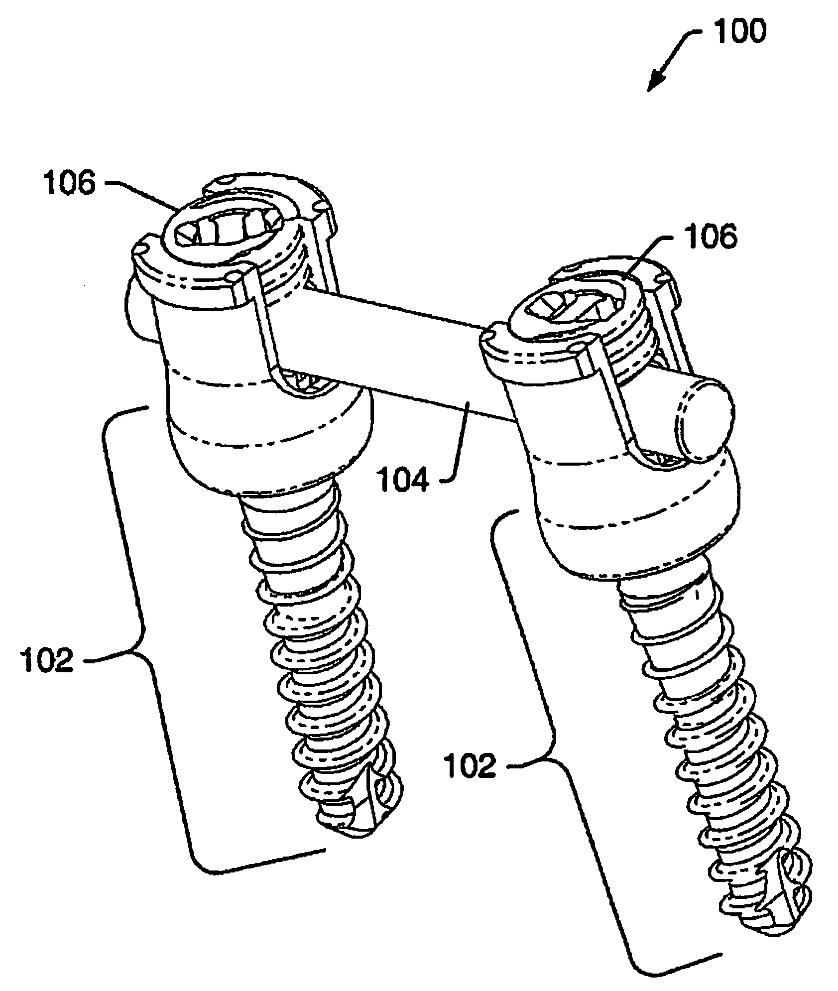
Dynamic stabilization system

a dynamic stabilization and vertebral body technology, applied in the field of dynamic stabilization systems and vertebral bodies, can solve the problems of limiting or controlling movement between, pain, injury or degenerative effect, discomfort, pain, or decreased function, and achieves the effect of facilitating recovery and more natural movement of the spin

Inactive Publication Date: 2009-01-01
ZIMMER SPINE INC
View PDF66 Cites 33 Cited by
  • Summary
  • Abstract
  • Description
  • Claims
  • Application Information

AI Technical Summary

Benefits of technology

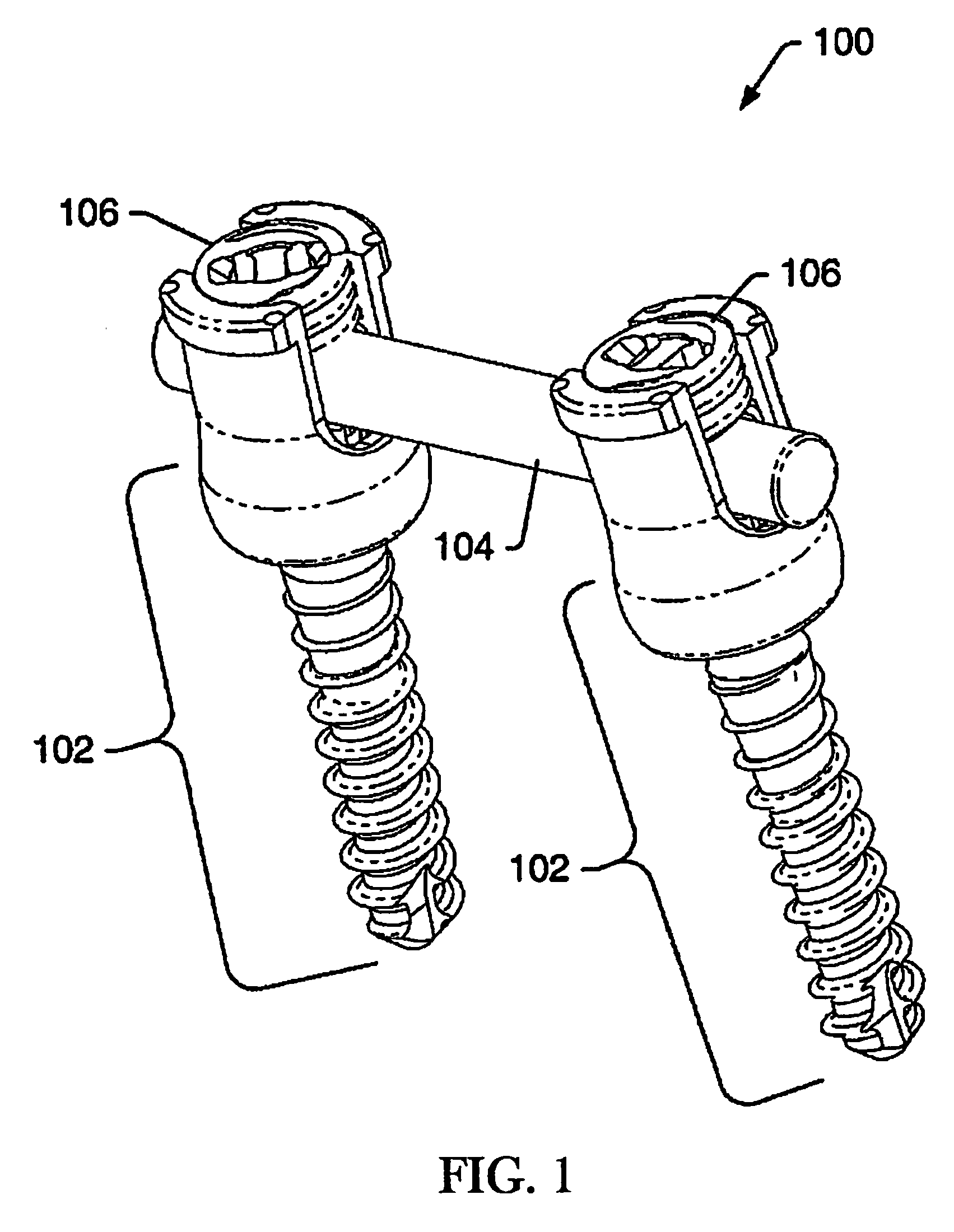
[0007]Embodiments of the present disclosure provide dynamic stabilization to facilitate recovery from spinal injuries and degenerative conditions. To achieve this and other goals, embodiments of the present disclosure have anchors implanted in vertebral bodies and an elongated member attached to the bone fasteners such that the elongated member can rotate relative to the bone fasteners. The resulting system allows for more natural movement of the spine.
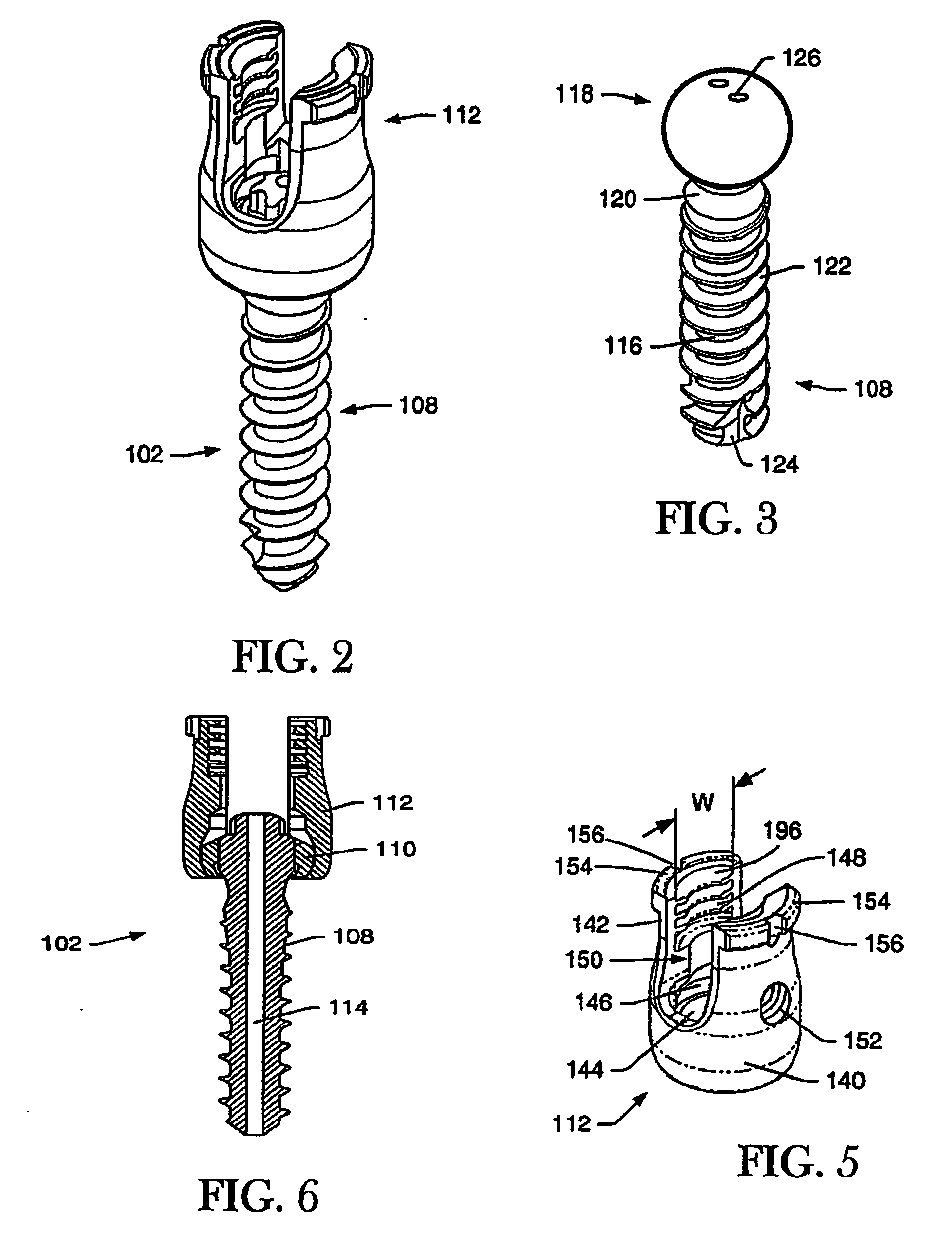
[0008]Unlike prior art bone fastener assemblies that fixed the vertebrae, embodiments of the present disclosure may be used to preserve movement between vertebrae in desired planes. Bone fasteners may be implanted in the pedicle of vertebral bodies. Friction reducing members may be positioned about the head of the bone fastener. Collars may be attached to the bone fasteners with the friction reducing member interposed, and an elongated member may be attached to connect two or more collars. Collars, friction reducing members, and / or bone fasteners may be configured to have a low friction coefficient. Vertebral bodies are able to move through some range because the elongated member can rotate relative to the collar, thus improving the range of motion of the spine without damaging adjacent vertebrae.
[0012]Yet another embodiment is directed to a method for dynamically stabilizing a spine by coupling a collar to an bone fastener in a bony tissue, positioning a portion of a elongated member in the collar, and connecting the closure member to the collar to maintain the collar in movable contact with the bone fastener. The collar may be configured such that dampened polyaxial motion of the elongated member relative to the bone fastener is preserved when the closure member is securely connected to the collar. The step of connecting the closure member to the collar to maintain the collar in selected contact with the bone fastener may be achieved by rotatably engaging the closure member with a modified thread portion, wherein the closure member is configured with a helically wound thread. The method may further include the step of positioning a friction reducing member inside the collar for low friction coefficient.

Problems solved by technology

In particular, it is sometimes necessary to limit or control movement between two or more vertebrae, either temporarily or permanently.
Prior art spinal stabilization systems run the risk that a rod too rigid to support the spine across the injured or degenerative disk will prevent desired degree of flexion, and may overcompensate by overextending, overflexing, or overtorquing the spine at adjacent vertebrae, which can result in discomfort, pain, injury, or degenerative effects.
Prior art spinal stabilization systems also run the risk that an elongated member is too flexible to support the spine across the injured or degenerative disk and will prevent the disk from healing properly, resulting in discomfort, pain, or decreased functionality.
In other words, if the stabilization system is too rigid, the stresses may be transferred to the adjacent vertebrae, resulting in additional injured or damaged disks, but if the rod is too flexible, the system may provide insufficient support, resulting in poor alignment, pain, longer healing times, or other undesirable effects.

Method used


Image

  • Dynamic stabilization system
  • Dynamic stabilization system
  • Dynamic stabilization system

Examples


Embodiment Construction

[0036]The disclosure and the various features and advantageous details thereof are explained more fully with reference to the non-limiting embodiments that are illustrated in the accompanying drawings and detailed in the following description. Descriptions of well known starting materials, processing techniques, components and equipment are omitted so as not to unnecessarily obscure the disclosure in detail. Skilled artisans should understand, however, that the detailed description and the specific examples, while disclosing preferred embodiments of the disclosure, are given by way of illustration only and not by way of limitation. Various substitutions, modifications, additions or rearrangements within the scope of the underlying inventive concept(s) will become apparent to those skilled in the art after reading this disclosure.

[0037]Reference is now made in detail to the exemplary embodiments of the disclosure, examples of which are illustrated in the accompanying drawings. Wherev...


PUM


Abstract

Embodiments of the disclosure provide a device and system for dynamic spinal stabilization. A collar has an opening for connection to a bone fastener implanted in bony tissue and a slot for receiving a portion of an elongated member. When the elongated member is seated in the slot and a closure member is securely connected to the collar, the collar is capable of selected rotation about the bone fastener to provide dampened motion of the stabilization system.

Description

FIELD OF THE DISCLOSURE[0001]This disclosure relates generally to stabilizing movement between bony tissues within a body, and in particular to systems and methods for stabilizing movement between vertebral bodies. Even more particularly, embodiments of the present disclosure relate to systems and methods for dynamic stabilization of vertebral bodies.BACKGROUND OF THE DISCLOSURE[0002]The human spine is a column of vertebrae separated by spinal discs that protects the spinal cord and various nerves and blood vessels and supports the torso. Under normal circumstances, the spine is capable of movement such as flexion, extension and torsion. However, in medical situations such as injury, trauma, stress, or disease (both acute and chronic) stabilization of at least a portion of the spine may be necessary for healing or therapeutic benefits. In particular, it is sometimes necessary to limit or control movement between two or more vertebrae, either temporarily or permanently.[0003]Modern s...

Claims


Application Information

Patent Timeline
Patent Type & Authority Applications(United States)
IPC IPC(8): A61B17/70A61B17/58A61B17/04
CPCA61B17/7032A61B17/7038A61B17/7037
Inventor ELY, SCOTT
Owner ZIMMER SPINE INC
Why Eureka
Try Eureka