Sulfur Evaporator

a sulfur evaporator and sulfur technology, applied in the direction of steam generation using steam absorption, fuel treatment, insect catchers and killers, etc., can solve the problem of substantial increase in the danger of greenhouse fires

Inactive Publication Date: 2009-01-08
ELSTEIN WERK M STEINMETZ
View PDF60 Cites 11 Cited by
  • Summary
  • Abstract
  • Description
  • Claims
  • Application Information

AI Technical Summary

Benefits of technology

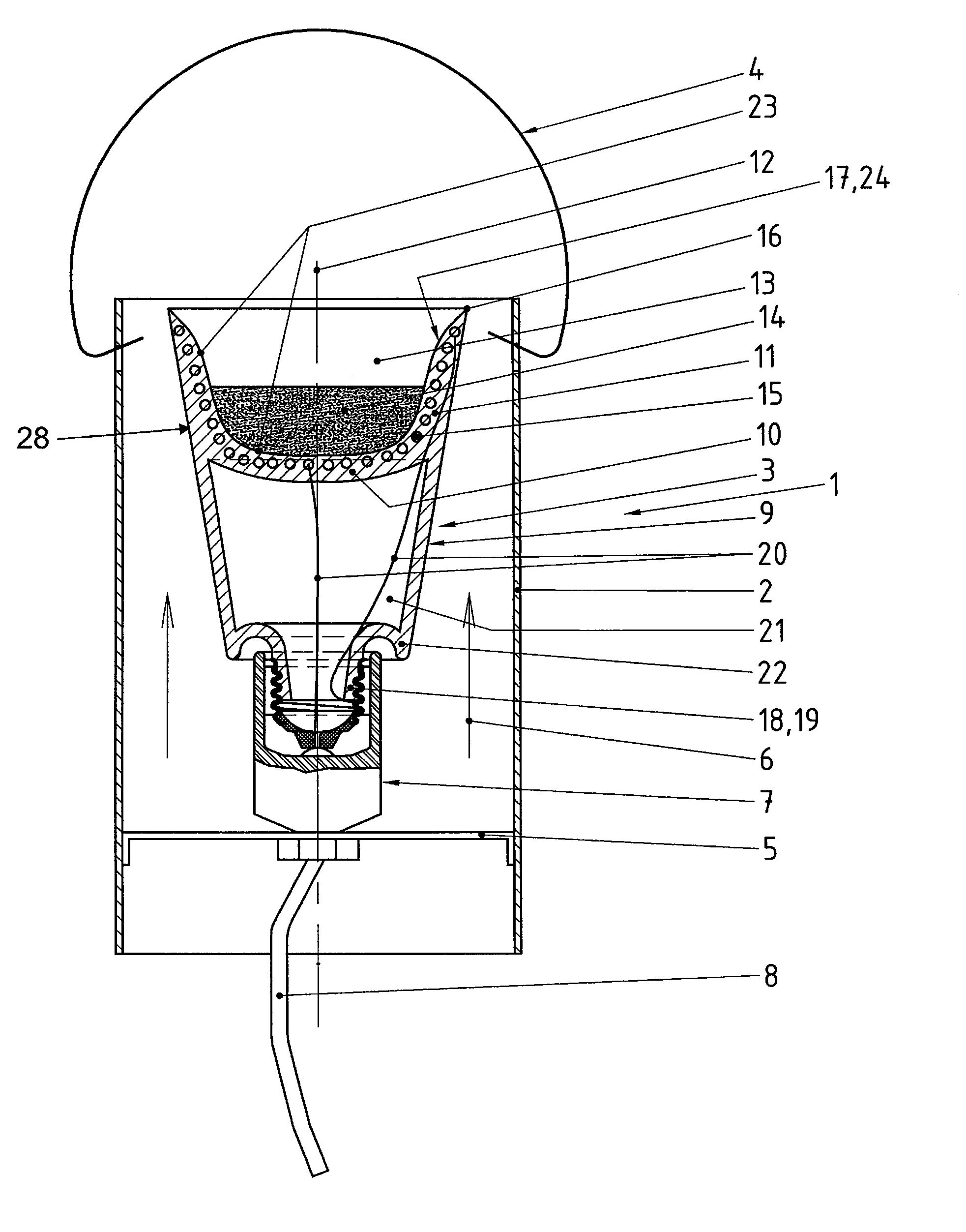
[0029]The container made of ceramic material at its lower end as seen in the upright operating position may include a dripping edge which protrudes in an axial direction. The dripping edge extends axially beyond the edge of the socket protruding in an upward direction. In this way, surplus sulfur in liquid form cannot enter the socket. Such surplus sulfur may result from the inner space being overfilled with sulfur and / or undesired transverse arrangement of the housing or when hitting upon the apparatus and thus causing a respecting displacement of the housing. This feature is an additional safety measurement for reducing and eliminating, respectively, the danger of fire.
[0030]The container can be designed to be conical in a way that its lower end diminishes in a downward direction as seen in the upright operating position of the evaporator. In this way, the inner space at the upper end may be designed to be respectively greater. There is a continuously changing cross-section between the outer wall of the conical container and the inner wall of the housing of the evaporator which additionally supports the chimney effect. It also results in turbulence of the moved air such that the sulfur which is evaporated is securely carried away and distributed. However, this does not mean that the container may also have a different design, for example a cylindrical, cup-like or mushroom-like design.
[0031]It is preferred if the container especially in the region of the inner space includes a glazing to design the surface of the body of ceramic material impervious to prevent sulfur from entering into the ceramic material. However, it is also possible to protect the entire surface of the container, meaning including its outer surface, by a glazing.

Problems solved by technology

In a temperature range which is approximately between 230° C. and 260° C., the sulfur attains its self-ignition temperature which substantially increases the danger of greenhouse fires.

Method used


Image

  • Sulfur Evaporator
  • Sulfur Evaporator
  • Sulfur Evaporator

Examples


Embodiment Construction

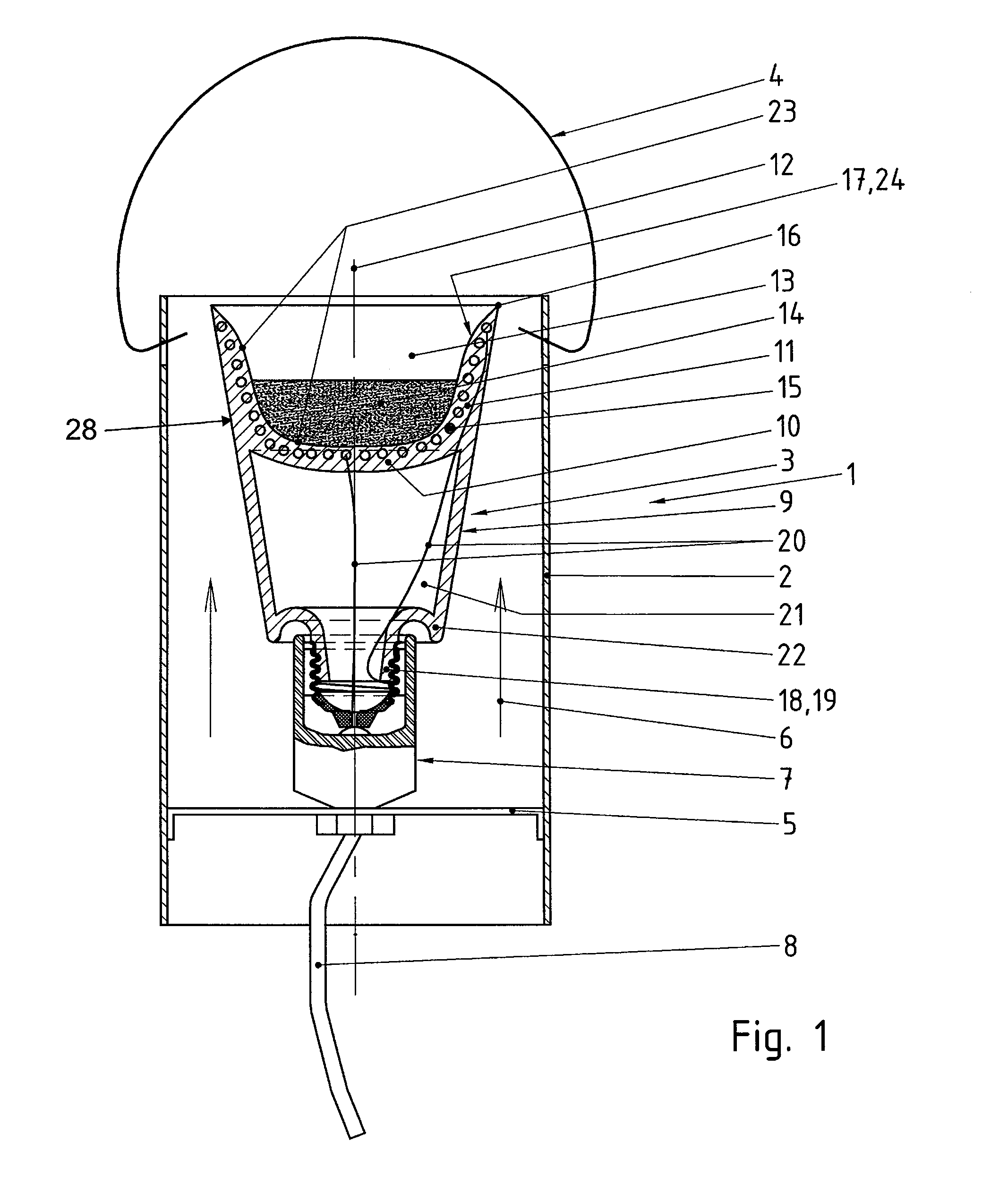
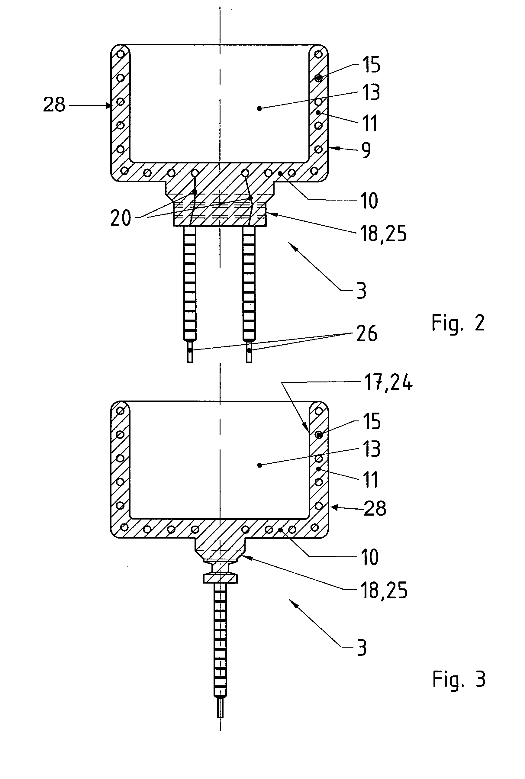
[0040]Referring now in greater detail to the drawings, FIG. 1 illustrates a novel apparatus 1 including a housing2. A sulfur evaporator 3 is arranged in the housing 2. The housing 2 is formed by tube sections made of metal which have an annular cross-section. The tube sections are designed to be open in an upward and a downward direction. A hanger 4 is located in the upper portion of the housing 2, and it serves to locate the apparatus 1, mostly in a greenhouse, by hanging. A transverse carrier 5 is fixedly located to the housing 2. The transverse carrier 5 has the design of a star or a bridge. The transverse carrier 5 only partly blocks the inner cross-section between the fumigation apparatus 3 and the inner wall of the housing 2 to allow for chimney-like airflow according to arrow 6 during operation of the apparatus 1. A socket 7 is located at the transverse carrier 5 in a stationary way. Power supply to the socket 7 is realized by a usual electric cable 8. The entire apparatus 1,...


PUM

PropertyMeasurementUnit
power consumptionaaaaaaaaaa

Abstract

A fumigation apparatus (1) includes a sulfur evaporator (3) including a heat source (28) and a container (9). The heat source (28) includes an electrically operated heating coil (15). The container (9) includes a wall (11) and an inner space (13). The inner space (13) is designed and arranged to store sulfur (14) to be evaporated therein. The container (9) substantially is made of ceramic material. The heat source (28) and the container (9) are designed as one common structural unit. The heating coil (15) at least partly is arranged in the wall (11) of the container (9) such that it is embedded in the ceramic material.

Description

CROSS REFERENCE TO RELATED APPLICATIONS[0001]This application claims priority to co-pending German Patent Application No. DE 10 2007 031 572.6 entitled “Schwefelverdampfer”, filed Jul. 6, 2007.FIELD OF THE INVENTION[0002]The present invention generally relates to a fumigation apparatus for evaporating sulfur.[0003]More particularly, the present invention relates to a sulfur evaporator including a heat source being designed as an electrically operated heating coil which is embedded in a ceramic material. The apparatus further includes a container including an inner space for storing sulfur therein.[0004]Usually, such apparatuses serve for evaporating pesticides, mixtures of pesticides and other remedies as they are used for fighting plant diseases. It is intended to bring the respective counter agent from the liquid form or solid form into vaporous form, and to distribute the vapor in a closed building, especially in a greenhouse. A main field of application for such apparatuses is t...

Claims


Application Information

Patent Timeline
Patent Type & Authority Applications(United States)
IPC IPC(8): A01M13/00B01D1/02
CPCA01M1/2077
Inventor SEWZYK, PETERERDMANN, WOLFGANG
Owner ELSTEIN WERK M STEINMETZ
Why Eureka
Try Eureka