Method and Apparatus for Controlling an Internal Combustion Engine

a technology of internal combustion engine and control method, which is applied in the direction of combustion engine, electric control, hot gas positive displacement engine plant, etc., can solve the problems that the intake air quantity sufficient to achieve the torque as required cannot be guaranteed, and achieve the effect of improving fuel consumption, fuel saving, and improving fuel consumption

Inactive Publication Date: 2009-01-08
HITACHI LTD
View PDF6 Cites 65 Cited by
  • Summary
  • Abstract
  • Description
  • Claims
  • Application Information

AI Technical Summary

Benefits of technology

[0008]According to the invention, it is possible to set a turbocharger and a variable intake valve so as to achieve an improvement in fuel consumption while meeting an intake air quantity required to an internal combustion engine. In an internal combustion engine, in which mirror cycle is performed, an improvement in fuel consumption is achieved by causing a variable intake valve to perform early closing or late closing but an intake air quantity sufficient to realize torque as required cannot be ensured because of a decrease in actual stroke volume. For this, application of a turbocharger is effective and a fuel saving benefit owing to mirror cycle can be expected while a supercharging effect brings about an increase in intake air quantity to ensure a target intake air quantity. Since the flow rate-supercharging pressure characteristic is fixed in ordinary turbochargers, however, supercharging pressure is determined singly for a target intake air quantity. When supercharging pressure is determined, a controlled variable of a variable intake valve for realization of a target intake air quantity is determined, so that an operating condition for production of mirror cycle effect is limited to a particular region. Here, by using a turbocharger, of which turbo flow rate is made variable, and a variable intake valve in combination to control the turbocharger so that with the target intake air quantity, supercharging pressure is increased in that range, in which a ratio of supercharging pressure and exhaust pressure is equal to or less than a predetermined value, it is possible to realize that operating condition, under which a fuel consumption effect can be produced to the maximum by mirror cycle, in a wide range. The reason why the ratio of supercharging pressure and exhaust pressure is limited to a range within the predetermined value is that in that region, in which exhaust pressure considerably increases as compared with supercharging pressure, pumping loss in intake and exhaust processes becomes large to bring about a decrease in fuel saving benefit determined by the relationship, which offsets the fuel saving benefit of mirror cycle. Also, since a variable intake valve is controlled on the basis of a target intake air quantity and supercharging pressure, it is possible to accurately realize torque as required.

Problems solved by technology

In an internal combustion engine, in which mirror cycle is performed, an improvement in fuel consumption is achieved by causing a variable intake valve to perform early closing or late closing but an intake air quantity sufficient to realize torque as required cannot be ensured because of a decrease in actual stroke volume.

Method used


Image

  • Method and Apparatus for Controlling an Internal Combustion Engine
  • Method and Apparatus for Controlling an Internal Combustion Engine
  • Method and Apparatus for Controlling an Internal Combustion Engine

Examples


Embodiment Construction

[0029]Embodiments of the invention will be described hereinafter with reference to the drawings.

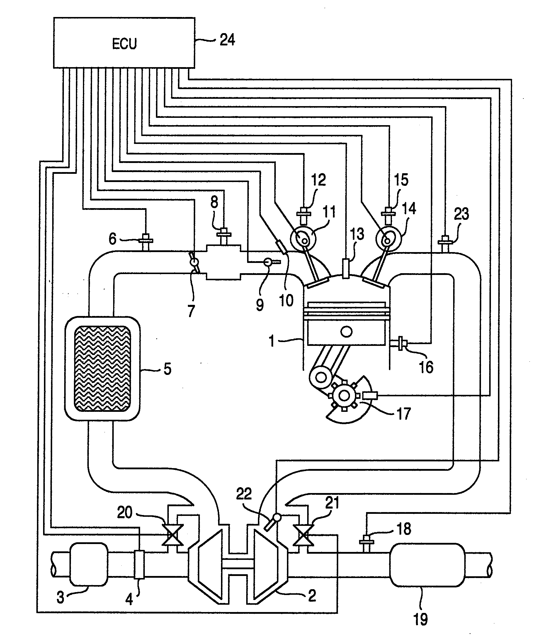
[0030]FIG. 1 is a view illustrating a first embodiment of the invention. A system according to the embodiment comprises an internal combustion engine 1. An intake flow passage and an exhaust flow passage are communicated with the internal combustion engine 1. An air cleaner 3 is connected to an upstream portion of the intake flow passage. An airflow sensor 4 is mounted downstream of the air cleaner to measure a flow rate of gases passing through the intake flow passage. A variable turbocharger 2 is connected to the intake flow passage and the exhaust flow passage. The variable turbocharger 2 comprises an exhaust gas turbine, by which energy of exhaust gases is converted into rotary motion of turbine blades, and a compressor, of which compressor blades connected to the turbine blades rotate to compress an intake air. A variable turbocharger means one capable of varying the relationship (tu...


PUM


Abstract

A control device for an internal combustion engine, which comprise a turbocharger, of which turbo flow rate is made variable, and an intake valve provided with a variable valve mechanism and in which mirror cycle is performed, the control device comprising: device, which calculates an intake air quantity per unit time and an intake air quantity per cycle on the basis of torque required to the internal combustion engine; device, which controls the turbocharger so that with the intake air quantity per unit time, supercharging pressure is further increased in that range, in which a ratio of supercharging pressure and exhaust pressure is equal to or less than a predetermined value; and device, which controls the variable valve mechanism on the basis of the supercharging pressure and the intake air quantity per cycle.

Description

BACKGROUND OF THE INVENTION[0001]The present invention relates to an internal combustion engine comprising a turbocharger, which is variable in flow rate, and a variable intake valve.[0002]Turbochargers, of which an exhaust turbine recovers, as rotational energy, thermal energy of exhaust gases discharged from an internal combustion engine, and in which a compressor provided coaxially with the exhaust turbine is used to compress an intake air of the internal combustion engine, are frequently used in conventional internal combustion engines. Since a turbocharger is mounted to enable a high output as compared with internal combustion engines, in which no turbocharger is mounted, and a cylinder volume required to realize the same output performance can be set to be small, it is possible to achieve a decrease in frictional loss and pumping loss, thus enabling reduction in fuel consumption.[0003]Under conditions of quick acceleration from low speed, however, sufficient supercharging cann...

Claims


Application Information

Patent Timeline
Patent Type & Authority Applications(United States)
IPC IPC(8): F02D45/00
CPCF02B29/0412Y02T10/42F02B37/18F02B37/22F02B37/24F02D13/0207F02D13/0219F02D13/0269F02D23/00F02D29/06F02D41/0002F02D41/0007F02D41/021F02D2041/001F02D2250/18Y02T10/144Y02T10/142F02B37/013Y02T10/12Y02T10/40
Inventor SUZUKI, KUNIHIKONEMOTO, MAMORU
Owner HITACHI LTD
Why Eureka
Try Eureka