Air Dryer for a Brake System

a technology of air dryer and brake system, which is applied in the direction of braking system, membrane, separation process, etc., to achieve the effect of reducing installation piping and minimizing weigh

Active Publication Date: 2009-01-08
NEW YORK AIR BRAKE CORP
View PDF25 Cites 9 Cited by
  • Summary
  • Abstract
  • Description
  • Claims
  • Application Information

AI Technical Summary

Benefits of technology

[0002]Air dryers employing membranes consisting of a permeable membrane capable of blocking the passage of nitrogen and oxygen molecules, but allowing water vapor molecules to pass through, as described in U.S. Pat. Nos. 6,719,825 and 5,525,143 amongst many others. In one variation of the technology, the air to be dried passes through the center of the membrane element. The membrane permits the passage of the water vapor to the outside of the membrane, but prevents the passage of the air to the outside of the membrane, thereby drying the air. To work effectively, the outside of the membrane must be kept dry and at a lower pressure than the inside, creating the partial pressure differential to drive the water vapor out. This is done by providing some fraction of the dry output air as a counter flow sweep air across the outside of the membrane. The sweep air can be provided by sweep air orifice(s) connecting the dry air in the membrane air dryer outlet to the sweep air chamber surrounding the outside of the membrane. The orifices control the volume of sweep air, typically 10-20% of the dryer capacity and create a pressure drop in the sweep air volume. The sweep air and entrapped moisture are expelled to atmosphere. U.S. Pat. No. 5,375,620 shows a self-adjusting flow metering device for the sweep air.
[0003]The present disclosure is directed to an air dryer, for example, for locomotives, packaged to fit inside a reservoir. The air dryer is generally cylindrical with a circular mounting flange on one end, which bolts to a similar mounting flange welded to the end of the reservoir. This arrangement solves the problem of finding room for the air dryer between main reservoir #1 and #2 on a locomotive, protects the air dryer and especially the vulnerable membrane element from the very high ambient temperatures (as high as 300 degrees F.) during operation of the locomotive in tunnels; protects the air dryer from environmental hazards, like flying stone ballast; eliminates installation piping, and minimizes weight.

Problems solved by technology

The controller delays closing the valve after the brake system terminates using air from the reservoir until the reservoir is recharged, and further delays closing for a predetermined time after the reservoir is recharged to fully purge the sweep volume in the membrane air dryer of all moisture.

Method used


Image

  • Air Dryer for a Brake System
  • Air Dryer for a Brake System
  • Air Dryer for a Brake System

Examples


Embodiment Construction

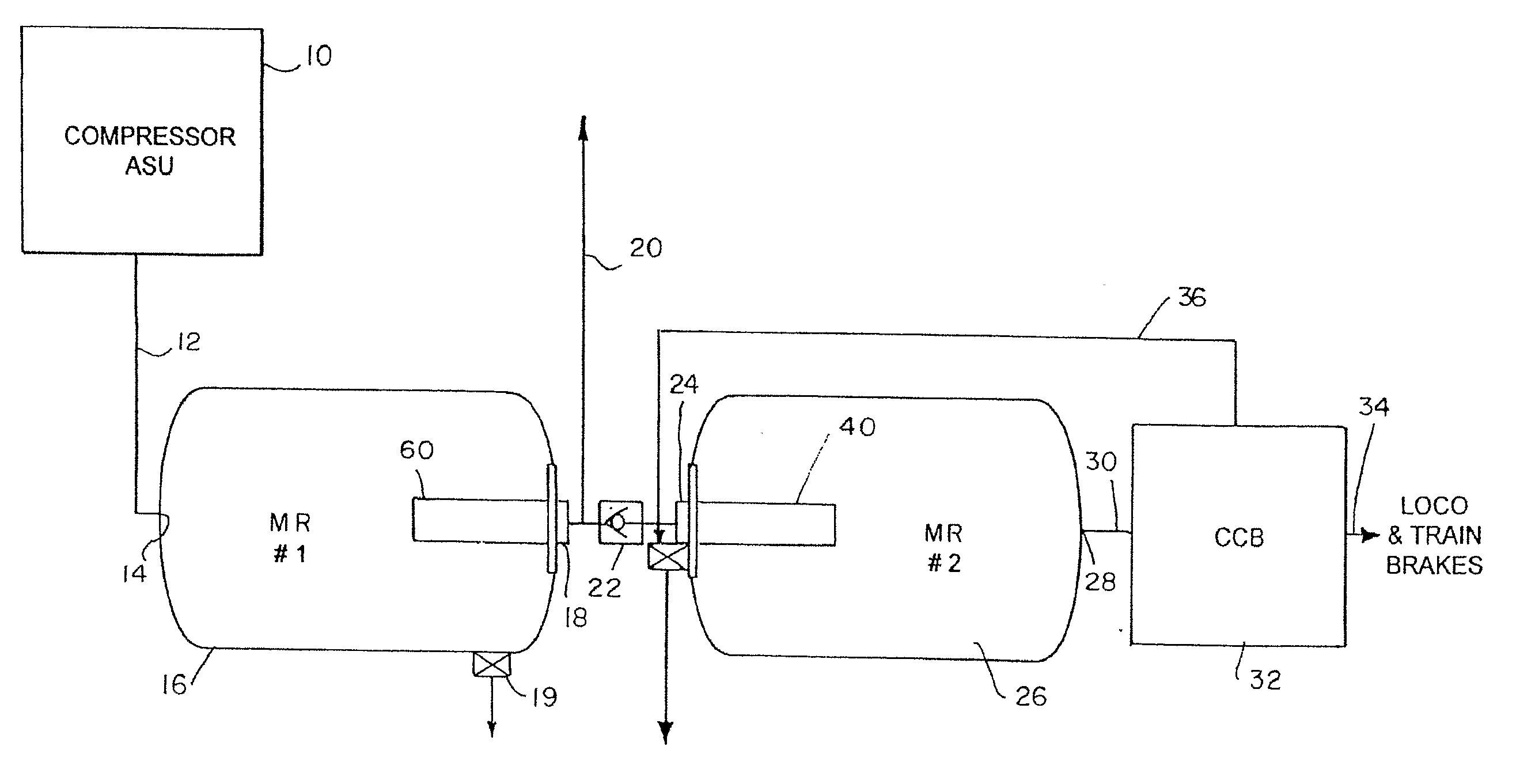
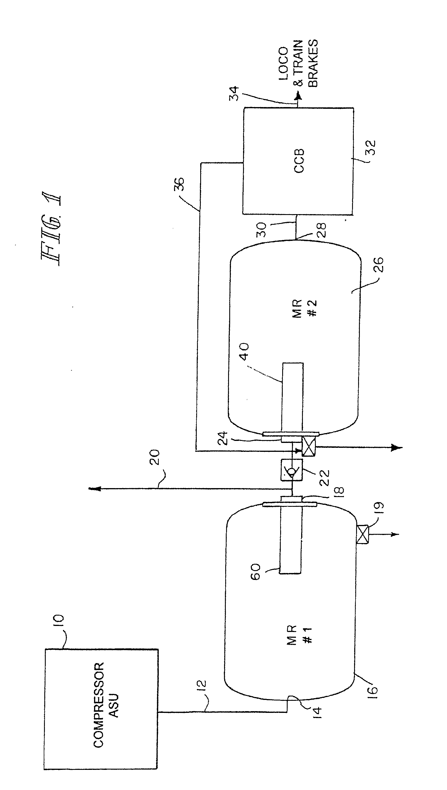
[0019]A locomotive brake supply and brake controller is shown in FIG. 1. A compressor 10 driven by the engines of the locomotive provides a source of compressed air through line 12 to inlet 14 of the first main reservoir MR. 16. The outlet 18 of the reservoir 16 is connected to other non-brake air consuming devices at line 20. The outlet 18 is also connected to the inlet 24 of the second main reservoir 26 via one-way check valve 22. The outlet 28 of the second main reservoir MR 26 is connected to a brake controller illustrated as a CCB computer controlled brake system 32. The outlet 34 of the computer controlled brake system 32 provides an appropriate pneumatic control signals for the locomotive and train brakes. As will be discussed below, the computer controlled brake system 32 provides, via line 36, control of the drain 54 of membrane air filter 40 within the main reservoir 26. As also will be discussed, control may also be provided to the drain valve 19 of the first main reservo...


PUM

PropertyMeasurementUnit
pressureaaaaaaaaaa
permeableaaaaaaaaaa
pressureaaaaaaaaaa

Abstract

An air dryer includes a housing with an air inlet, an air outlet and a liquid drain outlet; and a membrane separator having surfaces extending between a first and second ends of the membrane. A first passage in the housing is connected to the air inlet and air outlet at it respective ends and extends between the first and second ends of the membrane separator along the surfaces of the membrane separator. A second passage in the housing is connected to the drain outlet and air outlet at it respective ends and extends between the first and second ends of the membrane along a surface of the membrane separator. A valve is connected between the second passage and the drain outlet for controlling the draining of the liquid and sweep air flow through the second passage. The dryer is to be inserted in a reservoir at its inlet or outlet. A coalescing filter may be provided in the housing in series with the membrane separator and the housing would include a second drain for the coalescing filter.

Description

BACKGROUND AND SUMMARY OF THE DISCLOSURE[0001]The present invention relates generally to air dryers, and more specifically, to an air dryer for a brake system for vehicles.[0002]Air dryers employing membranes consisting of a permeable membrane capable of blocking the passage of nitrogen and oxygen molecules, but allowing water vapor molecules to pass through, as described in U.S. Pat. Nos. 6,719,825 and 5,525,143 amongst many others. In one variation of the technology, the air to be dried passes through the center of the membrane element. The membrane permits the passage of the water vapor to the outside of the membrane, but prevents the passage of the air to the outside of the membrane, thereby drying the air. To work effectively, the outside of the membrane must be kept dry and at a lower pressure than the inside, creating the partial pressure differential to drive the water vapor out. This is done by providing some fraction of the dry output air as a counter flow sweep air across...

Claims


Application Information

Patent Timeline
Patent Type & Authority Applications(United States)
IPC IPC(8): B01D53/22B60T7/20B60T10/00
CPCB01D53/268B01D63/02B60T17/004B01D2313/18B01D2313/90B01D2311/13
Inventor WRIGHT, ERICKOHAR, RICHARD
Owner NEW YORK AIR BRAKE CORP
Why Eureka
Try Eureka