Vehicle Derailing Prevention Device

a technology for preventing devices and vehicles, which is applied in the direction of anti-collision systems, underwater vessels, and steering of non-deflectable wheels, etc., and can solve problems such as affecting the safety of drivers, and the damping property of yaw motion of vehicles becoming deteriorated

Active Publication Date: 2009-01-08
TOYOTA JIDOSHA KK
View PDF9 Cites 18 Cited by
  • Summary
  • Abstract
  • Description
  • Claims
  • Application Information

AI Technical Summary

Benefits of technology

[0004]Incidentally, a known means for notifying the driver of the possibility of deviation upon the prediction of lane deviation as described above is a means for notifying the driver by applying a torque to a steering system. However, if the torque applied to the steering system upon the issue of the warning (which will be referr...

Problems solved by technology

However, if the torque applied to the steering system upon the issue of the warning (which will be referred to hereinafter as a warning torque) is kept constant, independent of driving conditions and ambient conditions of the vehicle, there will be cases where the warning torque is too weak to fully exercise the ...

Method used


Image

  • Vehicle Derailing Prevention Device
  • Vehicle Derailing Prevention Device
  • Vehicle Derailing Prevention Device

Examples


first embodiment

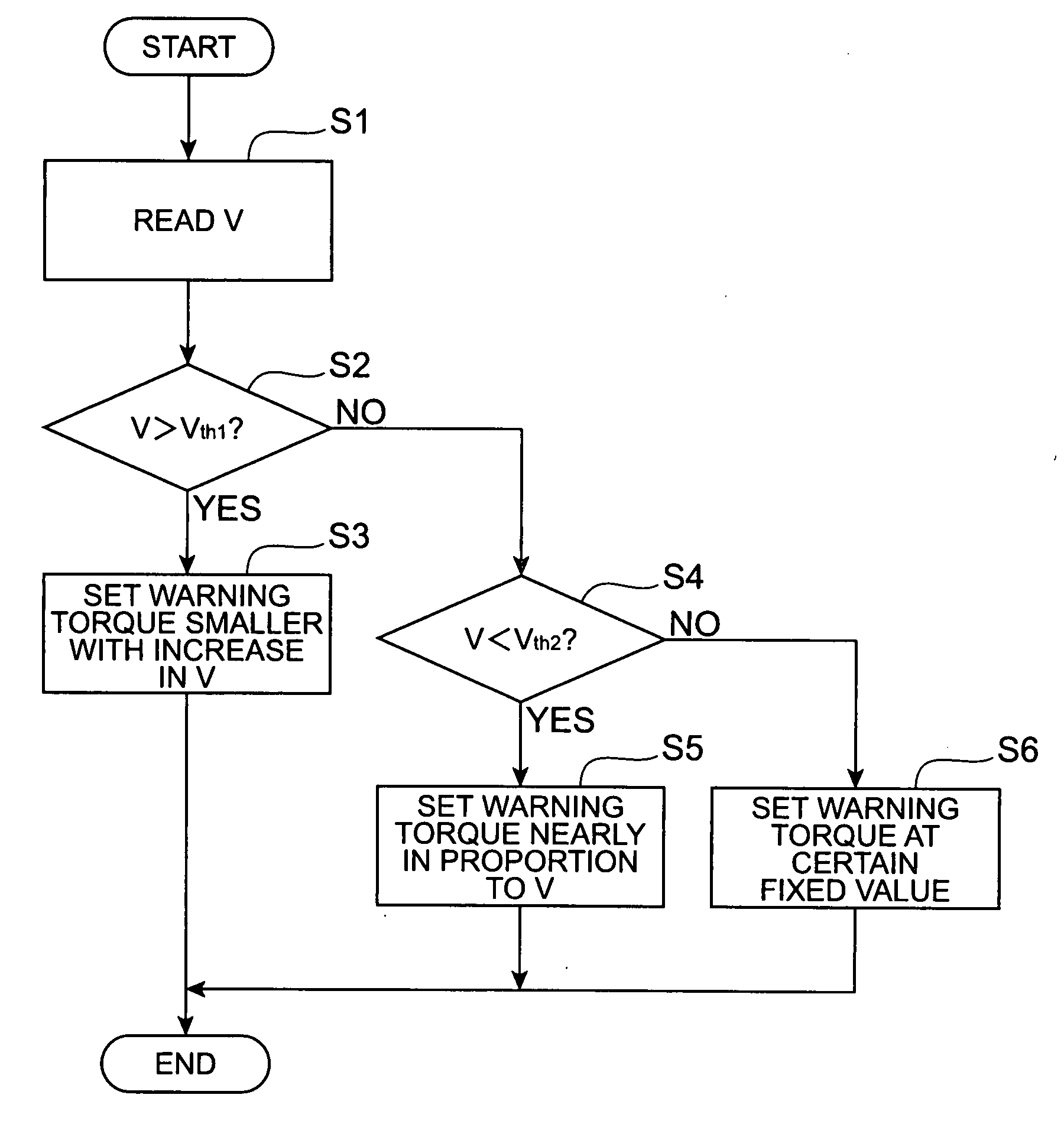
[0051]How to set the applied warning torque will be described below with specific examples. FIG. 3 is a flowchart showing the setting processing of the warning torque. The first step is to read a vehicle speed V from the output of vehicle speed sensor 12 (step S1). The next step is to determine whether the vehicle speed V is not less than a first threshold Vth (step S2). When the vehicle speed V is not less than the first threshold Vth1, the flow moves to step S3 to set the warning torque smaller with increase in the vehicle speed V, and then the processing is terminated. On the other hand, when the vehicle speed V is less than the first threshold Vth1, it is further determined whether the vehicle speed V is less than a second threshold Vth2 (step S4). This second threshold Vth2 is set to be smaller than the first threshold Vth1. When the vehicle speed V is less than the second threshold Vth2, the flow moves to step S5 to set the warning torque approximately in proportion to the veh...

second embodiment

[0057]Next, the second control embodiment will be described. FIG. 8 is a flowchart showing setting processing of the warning torque. The first step is to acquire lane width information of a driving lane on which the host vehicle is driving (step S11). This lane width information can be calculated, for example, from the white line recognition information acquired in the image processing part 21. At this time, in order to restrain influence of noise or the like of the recognition processing, it is preferable to use an average over a predetermined period of time (e.g., one second), or to perform a mask process of determining a change of lane width when the lane width continuously remains in a certain range, for example.

[0058]The next step is to set the warning torque on the basis of the lane width (step S12), and the processing is then terminated. FIG. 9 is a graph showing a setting example of the warning torque according to the lane width. The host vehicle is located closer to a paral...


PUM


Abstract

A vehicle speed V is read (step S1), V is compared with a first threshold Vth1 (step S2), and, when V is not less than Vth1, a warning torque is set smaller with increase in V (step S3). When V is less than Vth1, V is further compared with a second threshold Vth2 (step S4), and when V is less than Vth2, the warning torque is set approximately in proportion to the vehicle speed (step S5); when V is not less than Vth2 and is less than Vth1, the warning torque is set at a predetermined constant value (step S6).

Description

TECHNICAL FIELD[0001]The present invention relates to a vehicle deviation preventing apparatus arranged to detect a driving lane on which a host vehicle is driving, to estimate a path of the host vehicle, to determine whether the host vehicle will deviate from the driving lane, and, with a determination of a deviation, to issue a warning to a driver to prompt avoidance of the deviation.BACKGROUND ART[0002]There is a known technology of acquiring a road image in front of a vehicle with a camera mounted on the vehicle, detecting a driving lane on which the host vehicle is driving, by image processing, determining a possibility that the host vehicle will deviate from the driving lane, based on the detected driving lane information and an estimated path of the host vehicle, and, with a high possibility of a deviation, issuing a warning to a driver to prompt avoidance of the deviation by a steering operation or the like (e.g., cf. Japanese Patent Application Laid-Open No. 7-105498).[0003...

Claims


Application Information

Patent Timeline
IPC IPC(8): B60Q1/00B62D6/00B60R21/00B60W30/12B60W50/14B60W50/16B62D101/00B62D111/00B62D119/00G08G1/16
CPCB60W30/12B60W50/14G08G1/167B62D15/029G08G1/16B62D15/025
Inventor KATAOKA, HIROAKIKAWAKAMI, SEIJIIWAZAKI, KATSUHIKORATTAPON, CHUMSAMUTR
Owner TOYOTA JIDOSHA KK
Why Eureka
Try Eureka