Display device with touch panel
- Summary
- Abstract
- Description
- Claims
- Application Information
AI Technical Summary
Benefits of technology
Problems solved by technology
Method used
Image
Examples
first embodiment
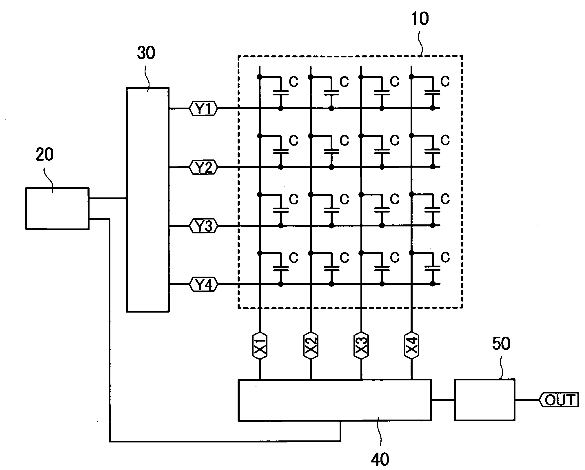
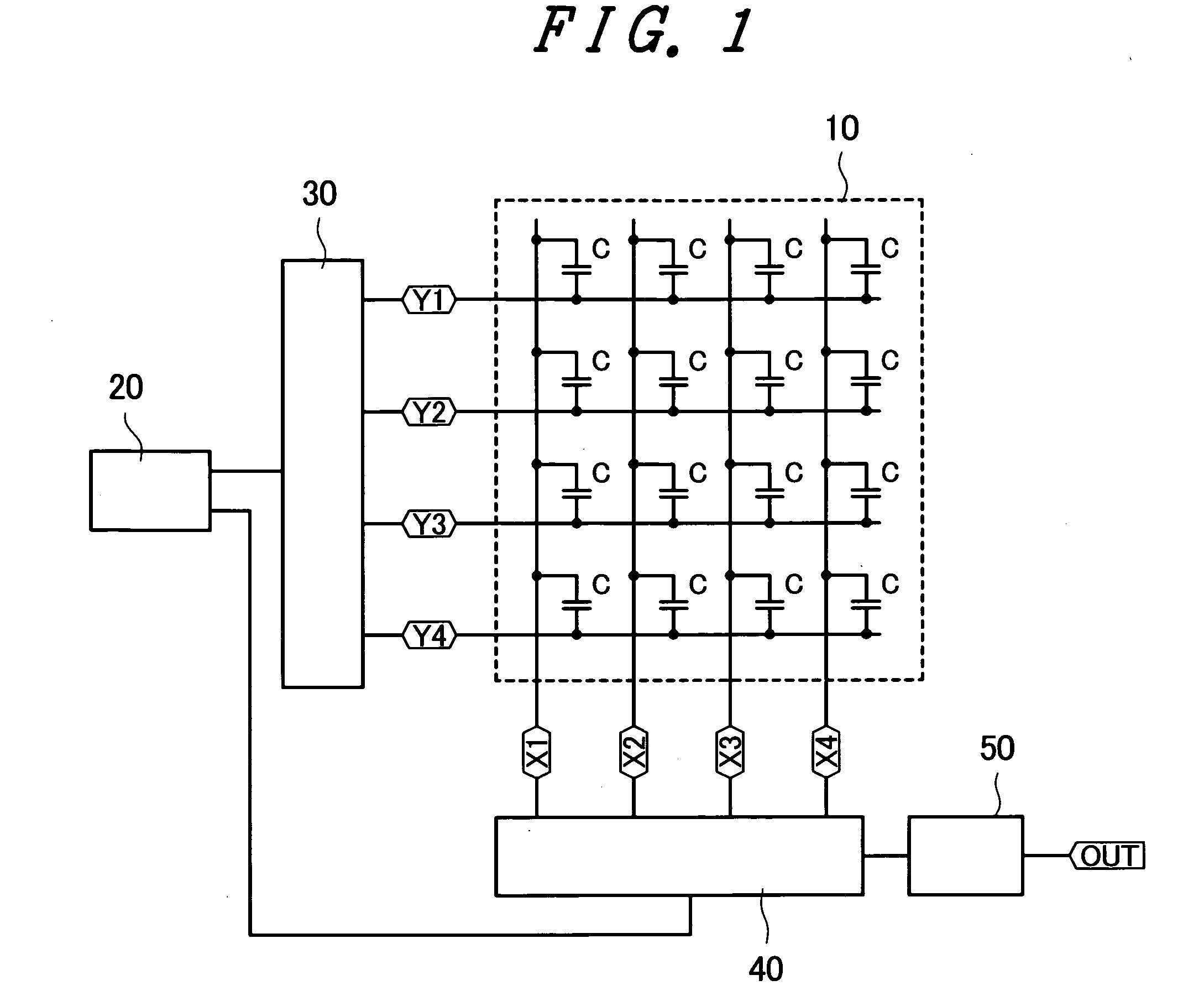
[0046]FIG. 1 is a block diagram showing the schematic structure of a touch panel used in a liquid crystal display device according to a first embodiment of the present invention.
[0047]In FIG. 1, reference numeral 10 denotes a touch sensor, 20 denotes a control circuit, 30 denotes a Y driving circuit, 40 denotes an X detection circuit, and 50 denotes a coordinate detection circuit. X1 to X4 denote X electrodes extending in a first direction (a Y direction in FIG. 1), Y1 to Y4 denote Y electrodes extending in a second direction (an X direction in FIG. 1), and C denotes coupling capacitors formed between the respective X electrodes and the respective Y electrodes.
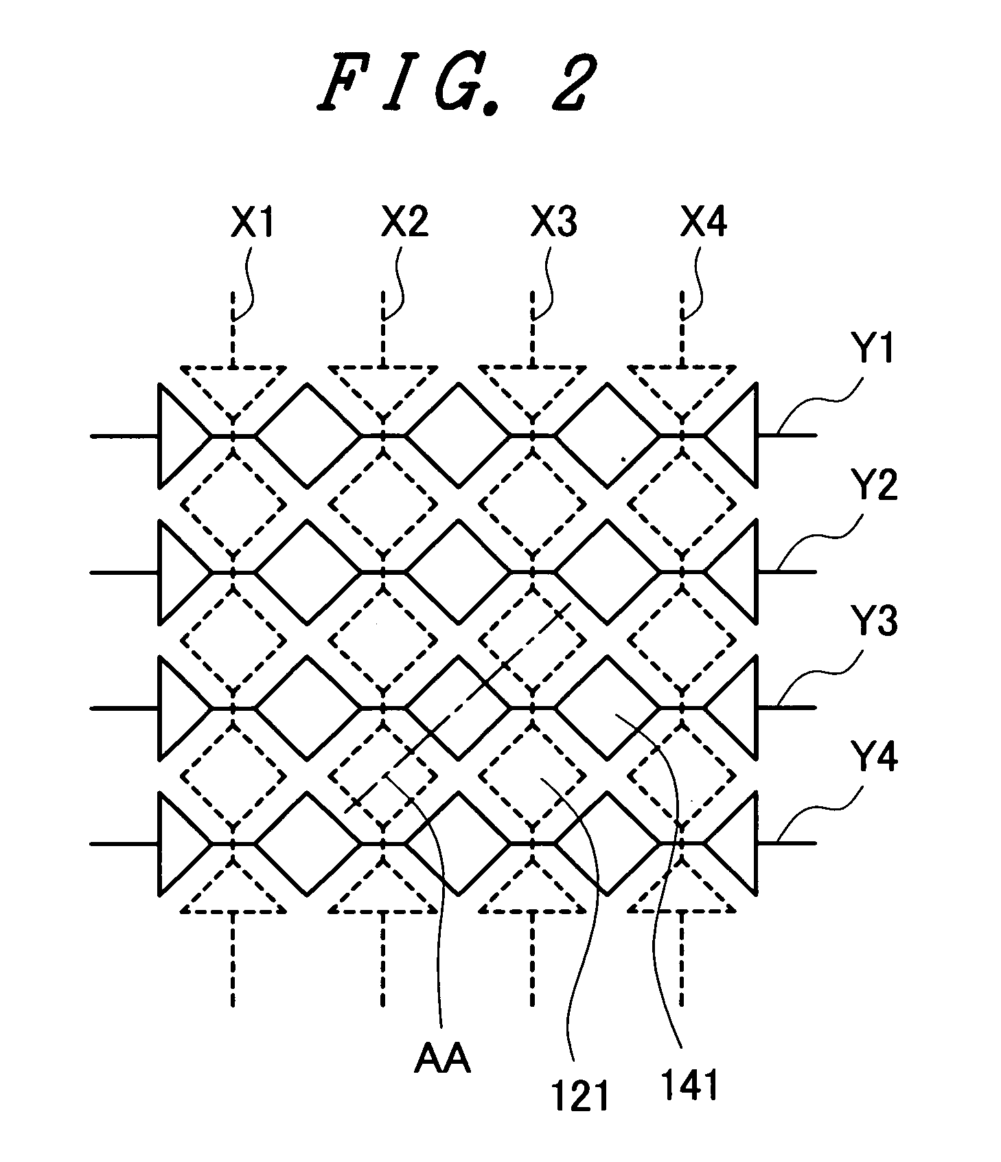
[0048]FIG. 2 is a diagram showing electrode shapes of the X electrodes and the Y electrodes shown in FIG. 1. As shown in FIG. 2, the X electrodes X1 to X4 have wide electrode patterns 121 among the Y electrodes Y1 to Y4. The Y electrodes Y1 to Y4 have wide electrode patterns 141 among the X electrodes X1 to X4.
[0049]FIG. 3 is ...
second embodiment
[0071]FIG. 8 is a block diagram showing the schematic structure of a touch panel used in a liquid crystal display device according to a second embodiment of the present invention.
[0072]In FIG. 8, reference numeral 10 denotes a touch sensor, 20 denotes a control circuit, 70 denotes a current detection circuit, and 80 denotes an electrode driving circuit.
[0073]In the first embodiment, the L level voltage is sequentially supplied to the respective Y electrodes in a time division manner and electric currents flowing to the respective X electrodes are detected to detect a coordinate position However, in the second embodiment, the control circuit. 20 controls a switch 90 and, in a period A, the electrode driving circuit 80 sequentially supplies the L level voltage to the respective Y electrodes in a time division manner and the current detection circuit 70 detects electric currents flowing to all X electrodes and, in a period B, the electrode driving circuit 80 sequentially supplies the L...
third embodiment
[0080]FIG. 11 is a block diagram showing the schematic structure of a touch panel used in a liquid crystal display device according to a third embodiment of the present invention.
[0081]In FIG. 11, reference numeral 10 denotes a touch sensor, 210 denotes a Y electrode selection circuit, 220 denotes an X electrode selection circuit, and 230 denotes a current detection circuit. The Y electrode selection circuit 210 and the X electrode selection circuit 220 have identical circuit configurations. However, in FIG. 11, only the circuit configuration of the Y electrode selection circuit 210 is shown.
[0082]The Y electrode selection circuit 210 and the X electrode selection circuit 220 have a scanning circuit 211 and a scanning circuit 212. The scanning circuit 212 turns off all switching elements SW3 in the period A and turns on all the switching elements SW3 in the period B.
[0083]The scanning circuit 211 sequentially controls, in a time division manner, ON and OFF of a switching element SW1...
PUM
 Abstract
Description
Claims
Application Information
 - R&D
- Intellectual Property
- Life Sciences
- Materials
- Tech Scout
- Unparalleled Data Quality
- Higher Quality Content
- 60% Fewer Hallucinations
Browse by: Latest US Patents, China's latest patents, Technical Efficacy Thesaurus, Application Domain, Technology Topic, Popular Technical Reports.
© 2025 PatSnap. All rights reserved.Legal|Privacy policy|Modern Slavery Act Transparency Statement|Sitemap|About US| Contact US: help@patsnap.com


