
Optical component and transceiver packaging

a technology of optical components and transceivers, applied in the field of optical modules, can solve the problems of replacing the entire component or the entire module, and achieve the effects of reducing the area inside the module, reducing the cost of replacement, and increasing the density of connections

Active Publication Date: 2009-01-08
II VI DELAWARE INC
View PDF7 Cites 56 Cited by
  • Summary
  • Abstract
  • Description
  • Claims
  • Application Information

AI Technical Summary

Benefits of technology

The invention is a system and method for optical packaging that allows for the creation of different products using the same architecture. It also enables the evaluation, repair, and replacement of components at a component level. The optical module includes a connection assembly and a fiber assembly with a receptacle holder and a modified connector that allows for easy removal of components. The module also includes an optical component and other components such as SERDES and controllers. The use of a ball grid array (BGA) to connect the modules to the printed circuit board increases the density of connections and speeds. The technical effects of the invention include improved flexibility, ease of evaluation and replacement of components, and higher speeds.

Problems solved by technology

As a result, damage to the fiber often results in the replacement of the entire component or of the entire module.

Method used


Image

  • Optical component and transceiver packaging
  • Optical component and transceiver packaging
  • Optical component and transceiver packaging

Examples


Embodiment Construction

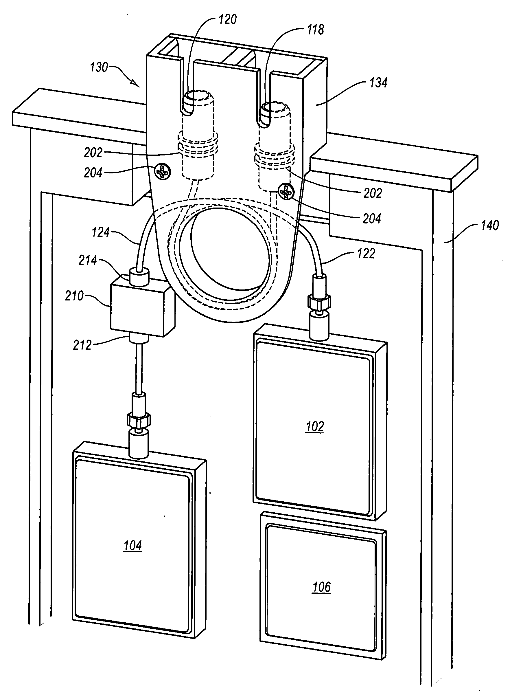
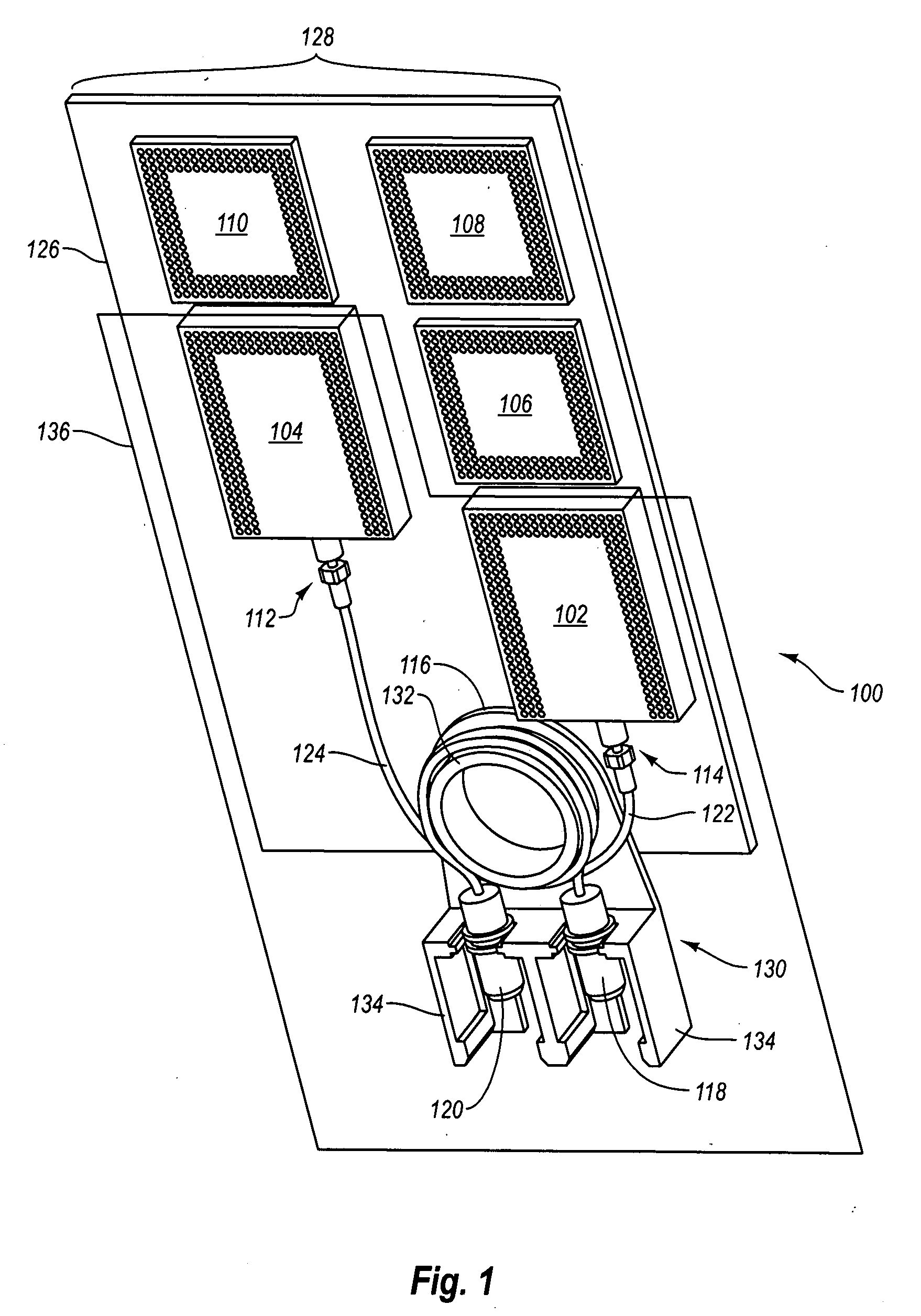
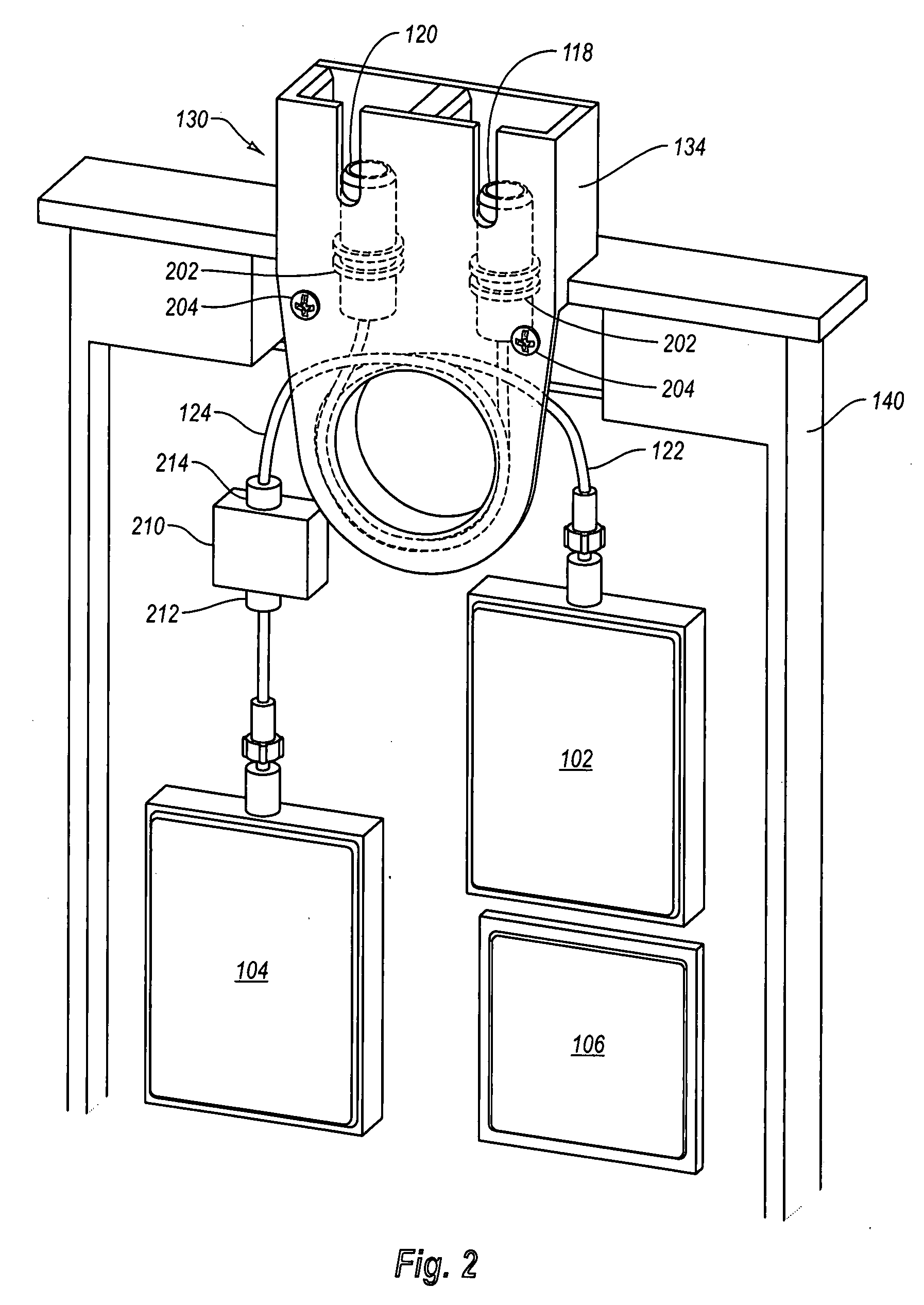
[0026]Embodiments of the invention relate generally to an optical module. The systems, methods, and architectures described herein can be used in various optical systems and solutions including, by way of example only, optical transceivers and optical transponders. The optical module described herein includes an architecture and layout that reduces or eliminates some of the problems found in conventional systems and architectures.

[0027]Advantageously, embodiments of the invention include an optical module that has replaceable components, an increased density of connections and or signal density, component protection, scalability for additional components, and the like or any combination thereof

[0028]The architecture disclosed herein enables high density integrated circuit (IC) packaging. For example, ball grid array (BGA) and fiber pig-tails can be used in transceiver and transponder applications. In one example, a BGA component inside of a module is adapted to include a receptacle ...


PUM


Abstract

An optical module and packaging thereof. A high speed optical module, such as a transceiver or transponder is disclosed. A fiber assembly including a receptacle, a fiber, and a modified connector are provided and enable an optical connection from inside of the optical component to outside of the component. Internally, the fiber assembly is detachable from an internal optical component. the optical component is connected to a PCB using a ball grid array. By detaching the fiber assembly, the optical component can be changed-out without damaging the fiber. The fiber is spooled inside the module to protect the fiber around a spooling assembly that is integrated with the receptacle holders that form part of the module's ports.

Description

CROSS-REFERENCE TO RELATED APPLICATIONS[0001]This application claims the benefit of U.S. Provisional Patent Application Ser. No. 60 / 948,395, filed Jul. 6, 2007 and entitled OPTICAL COMPONENT AND TRANSCEIVER PACKAGING, which application is incorporated by reference in its entirety.BACKGROUND OF THE INVENTION[0002]1. The Field of the Invention[0003]The present invention relates to optical modules such as optical transceivers and optical transponders. More specifically, the present invention relates to methods and systems for packaging a high speed optical component in an optical transceiver or an optical transponder.[0004]2. The Relevant Technology[0005]Optical modules including optical transceivers and optical transponders are used in a variety of applications including telecommunication and network applications. Optical modules often provide several advantages. For instance, optical signals are capable of high speeds compared to wired networks and are less susceptible to electromagn...

Claims


Application Information

Patent Timeline
Patent Type & Authority Applications(United States)
IPC IPC(8): G02B6/36
CPCG02B6/3825G02B6/4292G02B6/4246G02B6/3897
Inventor KIM, DAEHWAN DANIELDONOVAN, MARK J.
Owner II VI DELAWARE INC
Learn More