Method and member for measuring stress distribution of natural bone, synthetic bone, or member attached to them

a technology of stress distribution and natural bone, applied in the direction of force measurement by measuring optical property variation, instruments, prosthesis, etc., can solve the problems of bone damage, dynamic environmental change, loosening of implants,

Active Publication Date: 2009-01-08
NAT INST OF ADVANCED IND SCI & TECH
View PDF16 Cites 8 Cited by
  • Summary
  • Abstract
  • Description
  • Claims
  • Application Information

AI Technical Summary

Benefits of technology

[0019]The aforementioned structures of the invention allow the stress distribution of bone to be measured without omitted points in a visual manner accurately and in a variety of modes, using an inexpensive system.

Problems solved by technology

One of the issues facing the aging society that is gaining increasing attention involves problems concerning the bones, such as the changes in bone density or morphology accompanying the aging of body function, and damages to the bone due to falling accidents or the like.
For example, when an orthopedic implant such as an artificial joint is attached in the event of damage to a bone, the implant attached may cause a dynamic environmental change.
This could, under certain conditions, induce a change in the density or morphology of the bone, resulting in the loosening of the implant.
However, the number of such affixed strain gauges is limited and it has been impossible to conduct measurement without omitted points.

Method used


Image

  • Method and member for measuring stress distribution of natural bone, synthetic bone, or member attached to them
  • Method and member for measuring stress distribution of natural bone, synthetic bone, or member attached to them
  • Method and member for measuring stress distribution of natural bone, synthetic bone, or member attached to them

Examples


Embodiment Construction

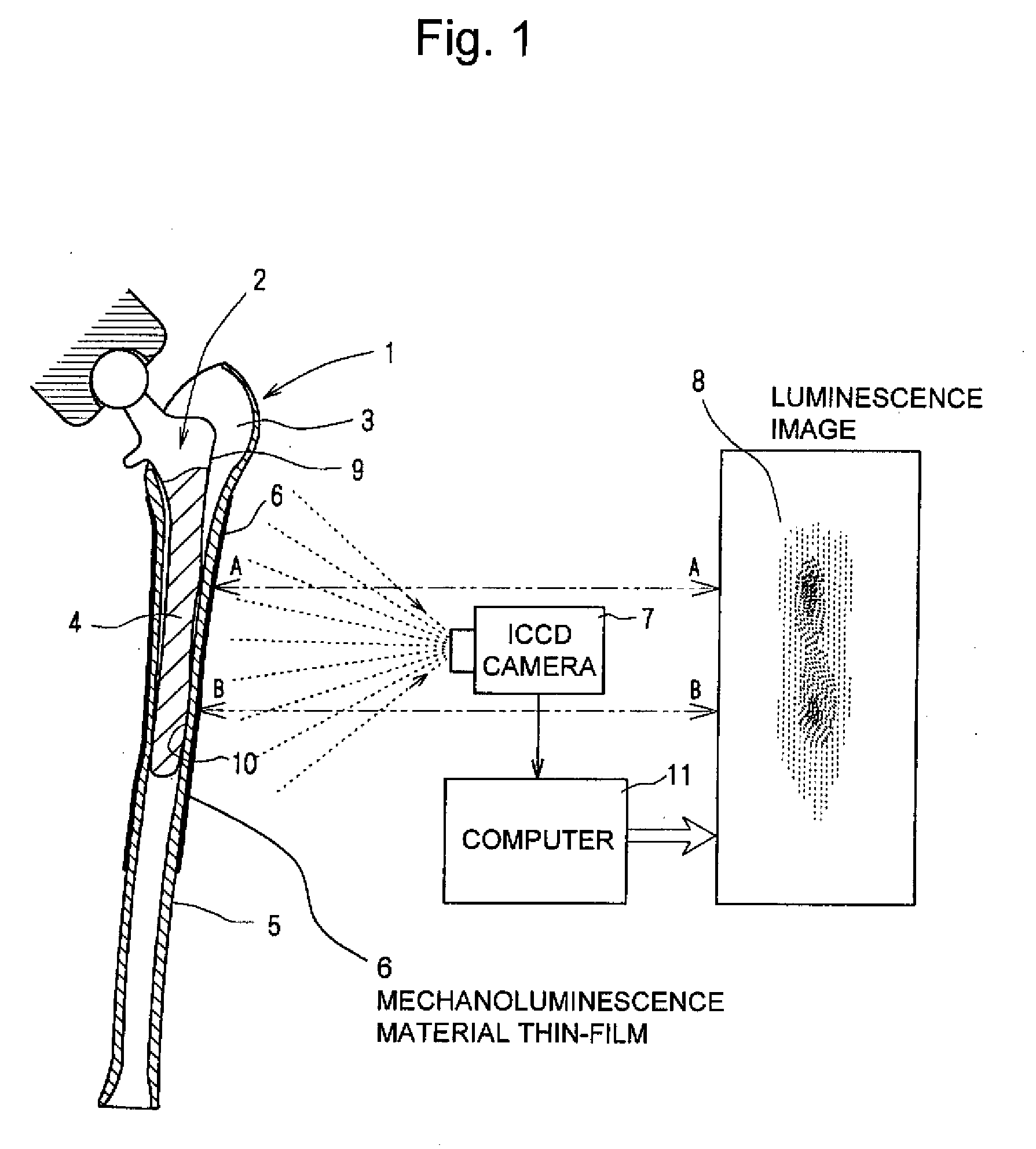
[0040]The present invention, when measuring the distribution of stress or strain (to be hereafter simply referred to as stress) of bone, employs the aforementioned inorganic materials that emit light based on mechanical energy, instead of the conventional method using infrared thermography. While such inorganic materials are disclosed in the aforementioned Patent Document 1, for example, they are described briefly in the following.

[0041]The mechanoluminescence material employed by the present invention comprises an inorganic base material in which a luminescence center is doped, the dope consisting of one or more of rare earths and transition metals that emit light as the electrons excited by mechanical energy return to ground state. Examples of the inorganic base material are oxides sulfides, carbides, and nitrides of melilite structure, FeS2 structure, wurtzite structure, spinel structure, corundum structure, or β-alumina structure. Of these, oxides having melilite structure, FeS2...


PUM


Abstract

When visualizing the stress distribution of natural bone, synthetic bone, or a member attached to either thereof without omitted points, in order to measure accurately in a variety of modes using an inexpensive system, a mechanoluminescence material thin film 6 is formed in advance on a bone material peripheral surface 5 in an appropriate area thereof including the portion where an insertion support portion 4 of an artificial hip prosthesis 2 is inserted into a hollow inside 3 of a damaged femur 1 or a synthetic bone simulating the damaged femur. The mechanoluminescence material thin film 6 portion is photographed over its entire circumference with an IICCD camera 7 from the external peripheral side thereof as or after the artificial hip prosthesis 2 is inserted. The obtained image is fed to a computer 11 to obtain a luminescence image 8. The computer 11 outputs the intensities of the received light in the form of an image as is, so that the luminescence image 8 can be obtained easily. Particularly, the data about the intensities of the received light can be used as stress/strain data virtually as is. Such method is also suitable for dynamic analysis.

Description

TECHNICAL FIELD[0001]The present invention relates to a method for measuring stress distribution of natural bone, synthetic bone, or a member attached to either thereof, by which the distribution of stress or strain on the bone or the like can be easily measured. The invention also relates to synthetic bone for stress distribution measurement and a member, such as an implant, that is attached to a natural or synthetic bone.BACKGROUND ART[0002]One of the issues facing the aging society that is gaining increasing attention involves problems concerning the bones, such as the changes in bone density or morphology accompanying the aging of body function, and damages to the bone due to falling accidents or the like. It is particularly important to overcome such problems to achieve “safe, secure, and high-quality life in an aging society.”[0003]For example, when an orthopedic implant such as an artificial joint is attached in the event of damage to a bone, the implant attached may cause a ...

Claims


Application Information

Patent Timeline
Patent Type & Authority Applications(United States)
IPC IPC(8): A61B5/103A61B19/00A61H33/00
CPCA61B5/4504A61B5/4528A61F2/36A61F2/3662A61F2/4657G09B23/32A61F2002/4632A61F2002/4666G01L1/241G09B23/30A61F2002/3631
Inventor HYODO, KOJIXU, CHAO-NAN
Owner NAT INST OF ADVANCED IND SCI & TECH
Why Eureka
Try Eureka