
Cardiac ablation devices and methods

a technology of ablation device and heart valve, which is applied in the field of medical devices and methods, can solve the problems of reducing the heart's ability to properly function as a pump, increasing the risk of acquiring a number of potentially deadly complications, and affecting the quality of life, so as to improve the performance and efficiency of energy emission, reduce the impedance, and increase the conductivity

Active Publication Date: 2009-01-08
ATRICURE
View PDF101 Cites 75 Cited by
  • Summary
  • Abstract
  • Description
  • Claims
  • Application Information

AI Technical Summary

Benefits of technology

[0015]In some embodiments, the at least one visualization member is removably coupled with at least one of the at least one energy transmission member, the at least one tissue securing member and the at least one guiding member. Also in some embodiments, the at least one visualization member may comprise at least one optic member for acquiring optic signals of an area to be visualized, and wherein the visualization member includes at least one inflatable member coupled with the visualization member at or near the optic member. For example, the inflatable member may provide a space in a body cavity and / or between at least two body tissues to enhance operation of the optic member. In some embodiments, the inflatable member includes an inflation port in fluid communication with an inflation lumen coupled with the visualization member for allowing introduction of a liquid or a gas to inflate the inflatable member. In some embodiments, the inflatable member reduces motion of the heart tissue when applied to the heart tissue.
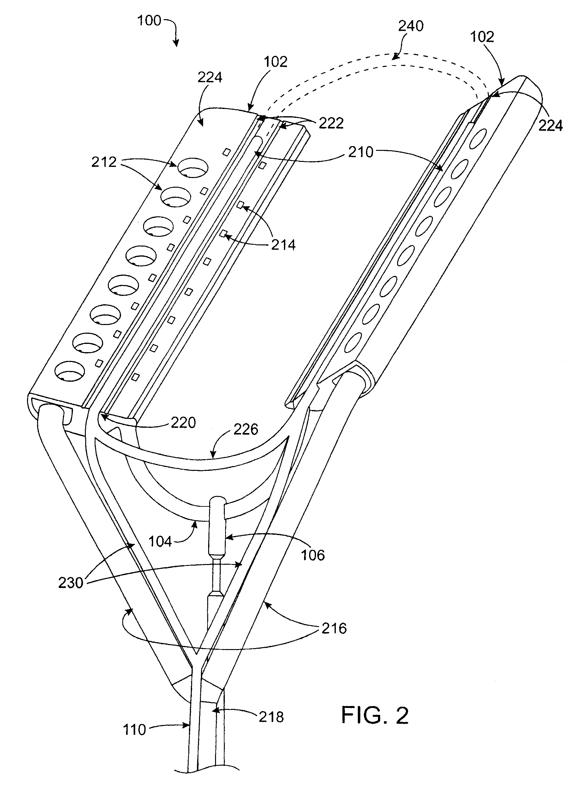
[0049]This allows ablation device construction to facilitate longer ablations by utilizing multiple connections to energy source. For example, if an energy source includes seven electrodes couple to a single plug to power seven ablation segments on the ablation device, the ablation device could include fourteen or twenty-one separate ablation segments. Each set of seven ablation segments would couple to a separate plug. In use, the first plug is inserted into the energy source and the first set of seven ablation segments is activated. Upon completion of treatment, possibly without moving the ablation device, a second region may be ablated by removing the first plug and inserting the second plug to activate the next seven ablation segments on the ablation device. This embodiment can result in a smaller less expensive energy source that is still capable of powering a long ablation device.

Problems solved by technology

This rapid quivering reduces the heart's ability to properly function as a pump.
Atrial fibrillation typically increases the risk of acquiring a number of potentially deadly complications, including thrombo-embolic stroke, dilated cardiomyopathy and congestive heart failure.
Quality of life is also impaired by common AF symptoms such as palpitations, chest pain, dyspnea, fatigue and dizziness.
Studies have shown, however, that warfarin tends to be under-prescribed for AF.
Patient compliance with warfarin is problematic, and the drug requires vigilant blood monitoring to reduce the risk of bleeding complications.
For example, currently available devices can be difficult to position and secure on epicardial tissue to perform an ablation.
Ablation devices often have no means for shielding ablative energy, to avoid unwanted burning of tissues in the vicinity of the heart, such as the esophagus.
Relatively few devices can be secured to epicardial tissue with sufficient force to allow for stabilization of the heart.
And many ablation devices may not be introduced by minimally invasive means, thus requiring an open surgical procedure.

Method used


Image

  • Cardiac ablation devices and methods
  • Cardiac ablation devices and methods
  • Cardiac ablation devices and methods

Examples


Embodiment Construction

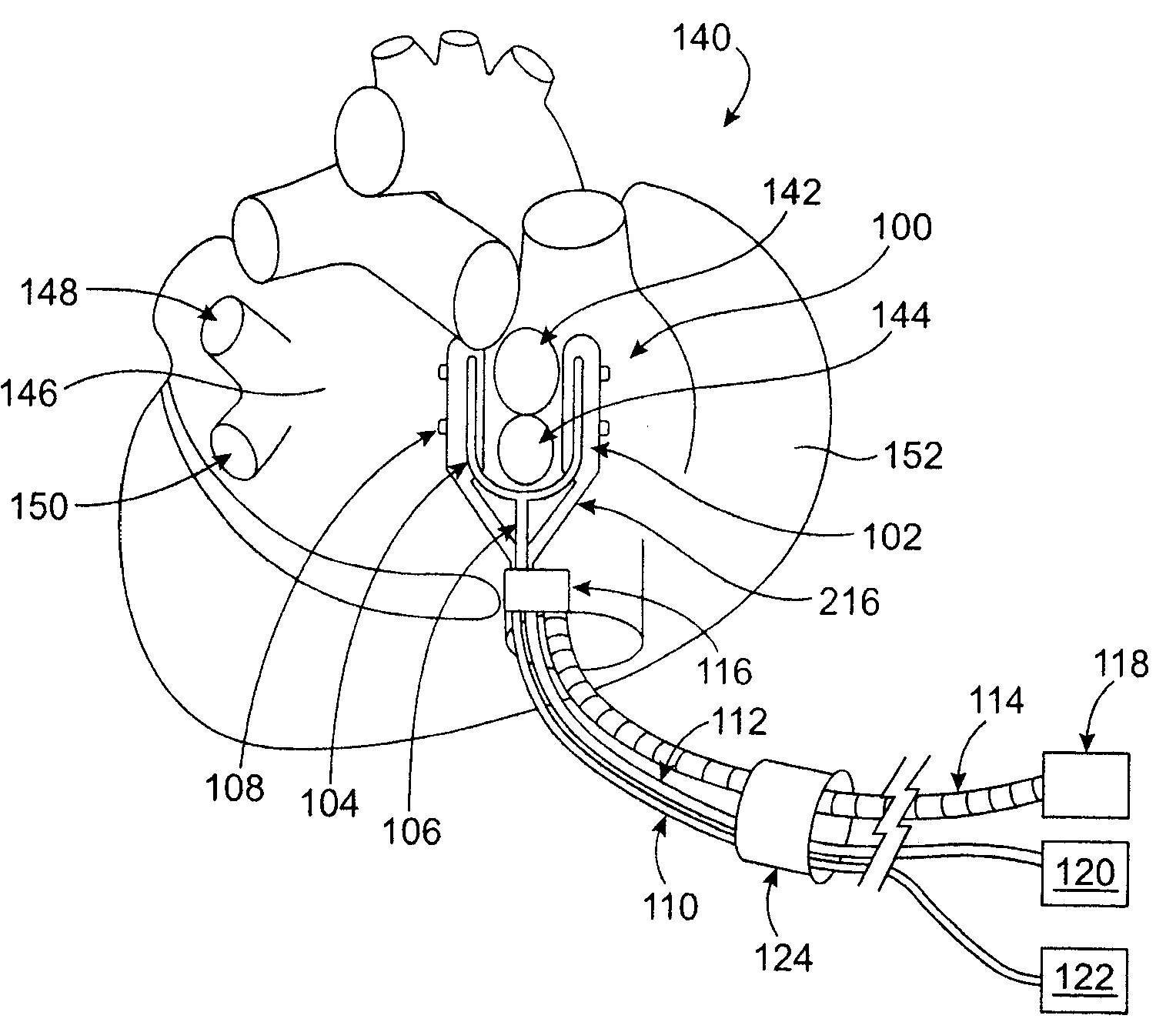
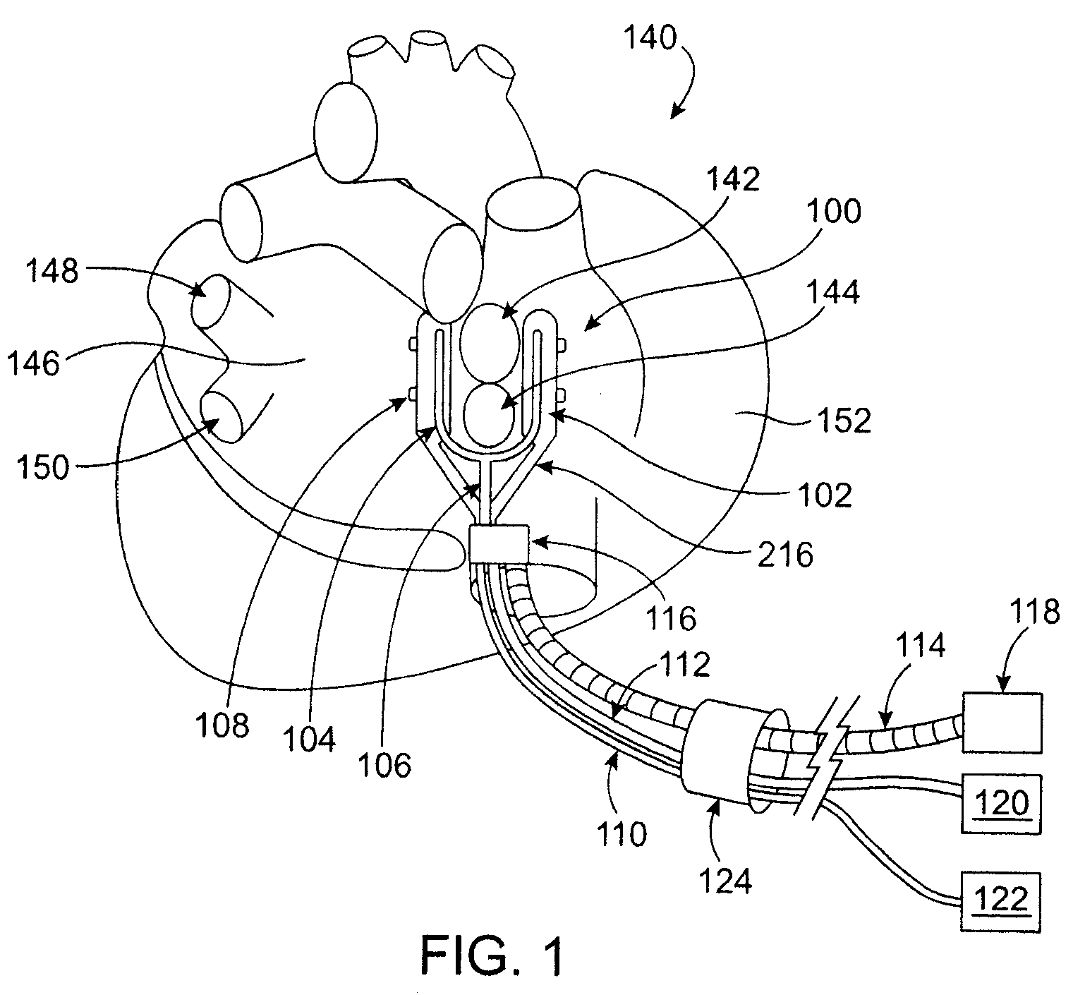
[0069]The present invention relates generally to medical devices and methods and more specifically to devices and methods for ablating cardiac tissue for treating cardiac arrhythmias such as atrial fibrillation. Ablation of cardiac tissue in various patterns has been shown to disrupt conduction pathways in the heart to ameliorate or eliminate AF or other arrhythmias. The devices and methods will often be used to ablate epicardial tissue in the vicinity of at least one pulmonary vein, but various embodiments may be used to ablate other cardiac tissues in other locations on a heart.

[0070]Generally, ablation devices of the invention include at least one tissue contacting member for contacting a portion of the epicardial tissue of a heart, securing means for securing the ablation device to the tissue and at least one ablation member coupled with the contacting member for ablating at least a portion of the tissue. In various embodiments, the devices have features which enable the device ...


PUM


Abstract

Devices and methods provide for ablation of cardiac tissue for treating cardiac arrhythmias such as atrial fibrillation. Although the devices and methods are often be used to ablate epicardial tissue in the vicinity of at least one pulmonary vein, various embodiments may be used to ablate other cardiac tissues in other locations on a heart. Devices generally include at least one tissue contacting member for contacting epicardial tissue and securing the ablation device to the epicardial tissue, and at least one ablation member for ablating the tissue. Various embodiments include features, such as suction apertures, which enable the device to attach to the epicardial surface with sufficient strength to allow the tissue to be stabilized via the device. For example, some embodiments may be used to stabilize a beating heart to enable a beating heart ablation procedure. Many of the devices may be introduced into a patient via minimally invasive introducer devices and the like. Although devices and methods of the invention may be used to ablate epicardial tissue to treat atrial fibrillation, they may also be used in veterinary or research contexts, to treat various heart conditions other than atrial fibrillation and / or to ablate cardiac tissue other than the epicardium.

Description

CROSS-REFERENCES TO RELATED APPLICATIONS[0001]The present application is a divisional of U.S. patent application Ser. No. 10 / 988,021 filed Nov. 12, 2004, now U.S. Pat. No. 7,399,300, which is a continuation-in-part of U.S. patent application Ser. No. 10 / 410,618 filed Apr. 8, 2003, which is a continuation in part of U.S. patent application Ser. No. 10 / 272,446 filed Oct. 15, 2002, which claims priority to U.S. Provisional Patent Application Ser. No. 60 / 337,070, filed Dec. 4, 2001, entitled “Methods and Devices for the Least Invasive Cardiac Surgery of Atrial Fibrillation.” application Ser. No. 10 / 988,021 also claimed priority to U.S. Provisional Patent Application Ser. No. 60 / 519,726, filed Nov. 12, 2003, entitled “Ablation Device.” The entire contents of these applications are hereby incorporated by reference in their entirety.BACKGROUND OF THE INVENTION[0002]The present invention relates generally to medical devices and methods. More specifically, the invention relates to devices an...

Claims


Application Information

Patent Timeline
Patent Type & Authority Applications(United States)
IPC IPC(8): A61B18/14A61M31/00A61B18/04A61B18/06A61B18/18A61B18/20A61B18/00A61F7/00A61N1/05
CPCA61B1/12A61B18/12A61B18/14A61B18/1402A61B18/1442A61B18/1477A61B18/148A61B18/1492A61B18/18A61B18/20A61B2017/00243A61B2017/22051A61B2017/2945A61B2018/00011A61B2018/00023A61B2018/00029A61B2018/00083A61B2018/0022A61B2018/00291A61B2018/00345A61B2018/00351A61B2018/00363A61B2018/00375A61B2018/00404A61B2018/00577A61B2018/00875A61B2018/00982A61B2018/0225A61B2018/0262A61B2018/126A61B2018/1425A61B2018/1432A61B2019/5231A61B2019/5276A61N1/0587A61B5/0536A61B2090/373A61B2090/378
Inventor BERTOLERO, ARTHUR A.IBRAHIM, TAMER
Owner ATRICURE
Learn More