Engine performance model

a technology of engine performance and model, applied in the field of engine performance models, can solve the problems of high complexity of modern gas turbine engines, and large number of iterative calculations, and achieve the effect of improving the accuracy of piecewise linear engine performance models

Inactive Publication Date: 2009-01-08
ROLLS ROYCE PLC
View PDF24 Cites 28 Cited by
  • Summary
  • Abstract
  • Description
  • Claims
  • Application Information

AI Technical Summary

Benefits of technology

[0006]An aim of the present invention is improve the a

Problems solved by technology

Modern gas turbine engines, such as high bypass ratio civil aeroengines, are highly complex machines.
Such performance models are, therefore, highly non-linear and can require large numbers of iterative calculations in order to arrive at

Method used


Image

  • Engine performance model
  • Engine performance model
  • Engine performance model

Examples


Embodiment Construction

[0106]Non-Linear Engine Performance Model

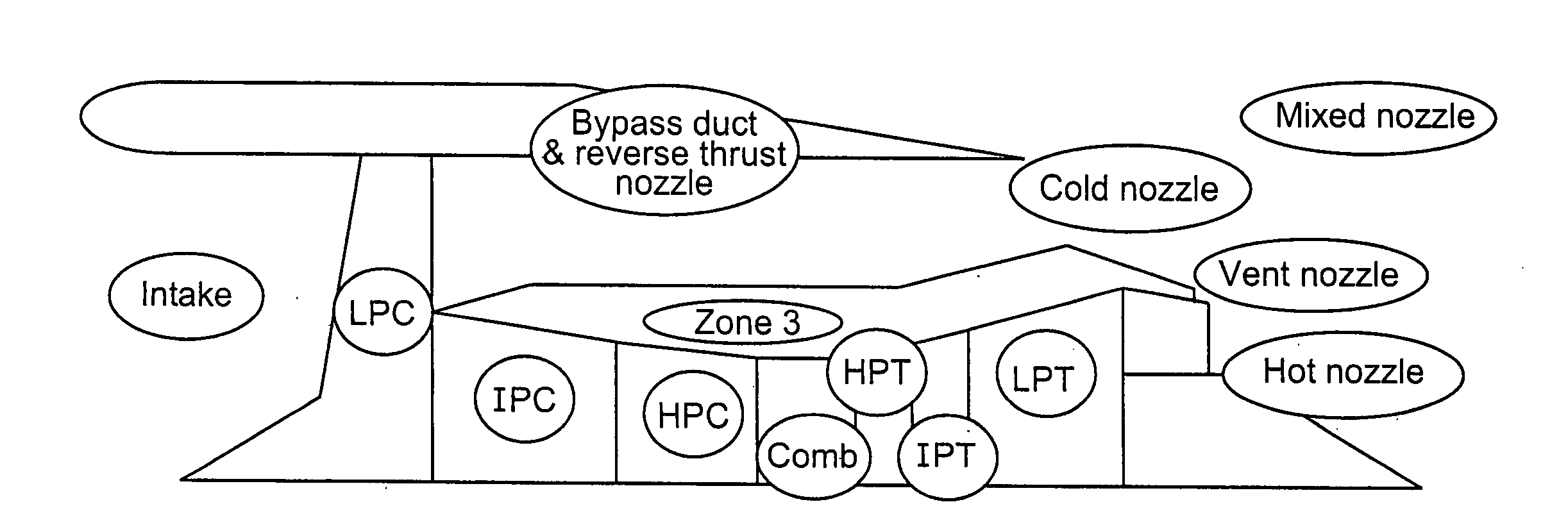
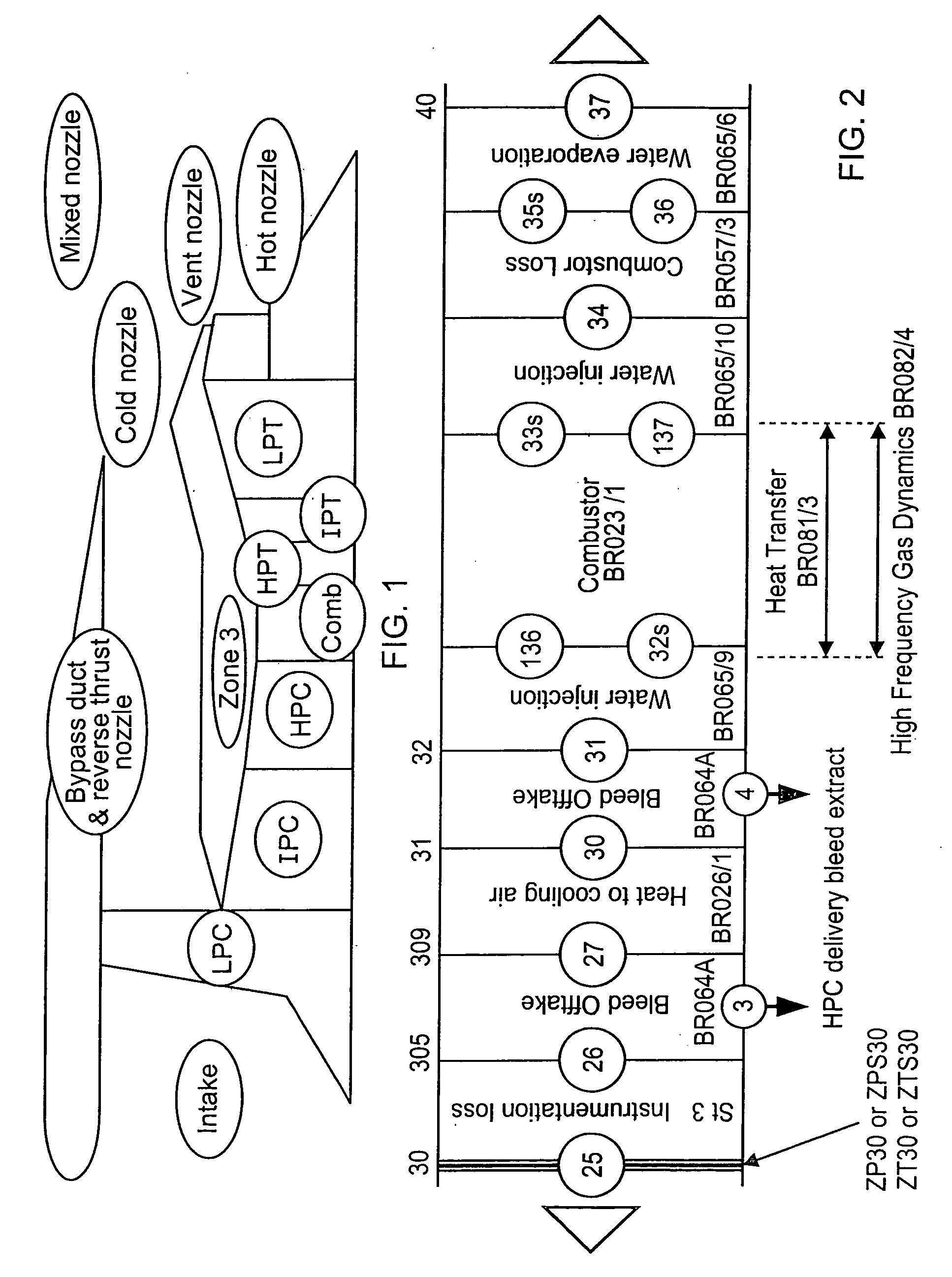
[0107]FIG. 1 shows a schematic diagram of the structure for a Rolls-Royce thermodynamic engine simulator. Each brick of the simulator is represented by a respective circled descriptor. FIG. 2 shows detail of the combustor (Comb) brick for the simulator of FIG. 1. The numbered features in FIG. 2 are calculation planes through the engine model where the working gas path fluid properties are calculated. Model bricks transfer the fluid properties from one plane to the next using non-linear thermodynamics.

[0108]The thermodynamic engine simulator shown schematically in FIG. 1 is an aero-thermal engine performance program capable of modelling steady state and transient operations throughout the flight envelope of an engine between engine idle speed and design speed.

[0109]However, the simulator is complex and highly non-linear, a typical solution time for one operating condition being at least about 25 ms.

[0110]Piecewise Linearised Model Representati...


PUM


Abstract

A method of constructing a piecewise linear engine performance model, comprises the steps of:
    • (a) providing a non-linear engine performance model which iteratively calculates engine performance variables y from a plurality of sub-models, each sub-model representing the performance of a component of the engine;
    • (b) defining a plurality of engine power conditions, each engine power condition being defined by one or more engine state variables x;
    • (c) for each of the engine power conditions, using the non-linear engine performance model to determine partial derivatives δy of the engine performance variables y with respect to engine control variables u and with respect to the engine state variables x, the values of the partial derivatives δy being determined so that, on integrating the partial derivatives δy, the error between steady state values for the engine performance variables y calculated by the non-linear engine performance model and steady state values for the engine performance variables y calculated from the integrated partial derivatives δy is reduced or eliminated; and
    • (d) constructing a piecewise linearised engine performance model in which calculation of the engine performance variables y involves combining each of the engine control variables u and the engine state variables x with the respective partial derivative δy.

Description

FIELD OF THE INVENTION [0001]The present invention relates to engine performance models.BACKGROUND OF THE INVENTION [0002]Modern gas turbine engines, such as high bypass ratio civil aeroengines, are highly complex machines. Because of the need for realistic development times and the need to reduce costs, components and systems of a new engine have to be developed simultaneously and often without access to an actual prototype engine.[0003]Engine performance models such as thermodynamic simulators are thus of crucial importance for engine development. Typically, they are functional models of the engine in which a plurality of linked modules or “bricks” model different components of the engine. The bricks have inputs and outputs connecting them to other bricks and each brick can be a complex model of the respective component in its own right. Such performance models are, therefore, highly non-linear and can require large numbers of iterative calculations in order to arrive at a solutio...

Claims


Application Information

Patent Timeline
IPC IPC(8): G06G7/48
CPCG05B17/02
Inventor ELLIS, SEAN PATRICKCHALLENER, MARK G.
Owner ROLLS ROYCE PLC
Why Eureka
Try Eureka