
Muffler for small engine

Inactive Publication Date: 2009-01-15
HIRAOKA MFG
View PDF6 Cites 27 Cited by
  • Summary
  • Abstract
  • Description
  • Claims
  • Application Information

AI Technical Summary

Benefits of technology

[0044]A muffler for a small engine according to further another embodiment, includes: a first expansion chamber (12) for exhaust gas having an exhaust gas inlet (11) being connected to the exhaust gas outlet of the engine; a second expansion chamber (15) which is partitioned from the first expansion chamber (12) by a partition plate (14); and a third expansion chamber (18) having an exhaust gas outlet (17) being communicated with the second expansion chamber (15) through a second communicating hole (16) on the partition plate (14). A first heat resistant mesh catalyst (19) is disposed on the exhaust gas inlet (11). A convex part (14d) having an exhaust gas outlet (14c) and protruding toward the second expansion chamber (15) is made in an integral molding manner. An exhaust gas purifier (20) composed of a heat resistant knit fabric (20a) coated with a catalyst for purifying the exhaust gas is installed on an exhaust gas inlet side on the side of the first expansion chamber (12) of the convex part (14b). A heat resistant cover (20b) having at least one exhaust gas outlet (20d) is disposed for covering the first exhaust gas purifier (20) from the first expansion chamber (12).
[0045]The muffler for a small engine according to further another embodiment, includes: the first expansion chamber (12) for the exhaust gas having the exhaust gas inlet (11) being connected to the exhaust gas outlet of the engine; and the second expansion chamber (15) being partitioned from the first expansion chamber (12) by the partition plate (14) having the first communicating hole (13). The first heat resistant mesh catalyst (19) is disposed on the exhaust gas inlet (11). The first exhaust gas purifier (20) composed of the heat resistant knit fabric (20a) coated with the catalyst for purifying the exhaust gas is disposed on the first communicating hole (13) on the partition plate (14). An outside air suction pipe (30) is disposed through the second expansion chamber (15). A portion of the outside air suction pipe facing to the first exhaust gas purifier (20) is composed of a double pipe. An end of the outside air suction pipe penetrates an outer wall and is communicated with an outside air. A plurality of suction holes (30b) are bored on an outer pipe of a double pipe (30

Problems solved by technology

However, in a conventional muffler of an engine as shown in FIG. 21, for example, because the exhaust gas purifier 5 is constituted by the honeycomb-like stainless steel support body coated with the catalyst for purifying exhaust gas, there is a problem that the manufacturing process is complicated and that a manufacturing cost is high.
There is a problem that a manufacturing process is complicated and that the manufacturing cost is high.
In the exhaust gas muffler of a 2-stroke engine as described in the patent document 2, because the exhaust gas inlet is not provided with the heat resistant mesh catalyst and the exhaust gas outlet is not provided with the heat resistant mesh catalyst, there is a possibility that sparks blow out from the exhaust gas outlet when the engine is under operation.
In the exhaust gas muffler of a 2-stroke engine as described in the patent document 3, because the exhaust gas inlet is not provided with the heat resistant mesh catalyst and the exhaust gas outlet is not provided with the heat resistant mesh catalyst, there is a possibility that sparks blow out from the exhaust gas outlet while the engine is under operation.
In the muffler for an engine as described in the patent document 5, because the cylindrical spark arrestor made of the cylindrical wire mesh is retained in a state fixed between the end of the tail pipe and the inner surface of the attaching body of the exhaust gas muffler, it is difficult to replace the spark arrestor with a new one.
In the exhaust gas muffler for a small engine as described in the patent document 6, because the catalyst which has a function of re-burning the unburned gas in the exhaust gas through the oxidation reaction, by coating the catalyst to the surface of the passage in the honeycomb structure composed of the stainless steel, a manufacturing process is complicated and a manufacturing cost is high.
In the exhaust gas muffler for a small engine as described in the patent document 7, while the cylindrical oxidation catalyst composed of the metal carrier is disposed as an exhaust gas purifier so as to protrude in the first expansion chamber and the second expansion chamber, there is a problem that a manufacturing cost of the cylindrical oxidation catalyst is high.
Meanwhile, because between the inner wall panel and the outer wall panel which form the double wall part, the exhaust gas flows to the outlet opening disposed on the outer wall panel and the outer wall panel is heated thereby, there is a problem that the double wall part does not have an effect preventing the outer wall of the muffler from being heated.
Further, because the muffler is partitioned to two parts of the body housing and the lid housing, and the ceramic cloth, the cloth catalyst and the wire mesh made of the stainless steel are stacked in turn and joined to whole the inner surface of each housing, there is a problem that a structure of the catalyst in the muffler is complicated and a manufacturing cost is high.
In a silencer as described in the patent document 9, because a separator which divides the silencer to two parts is not provided with a catalyst for purifying exhaust gas, there is a problem that a purifying effect on the exhaust gas is insufficient.

Method used


Image

  • Muffler for small engine
  • Muffler for small engine
  • Muffler for small engine

Examples


Embodiment Construction

[0072]Hereunder, a detailed description is made referring to the drawings on the embodiments of the present invention.

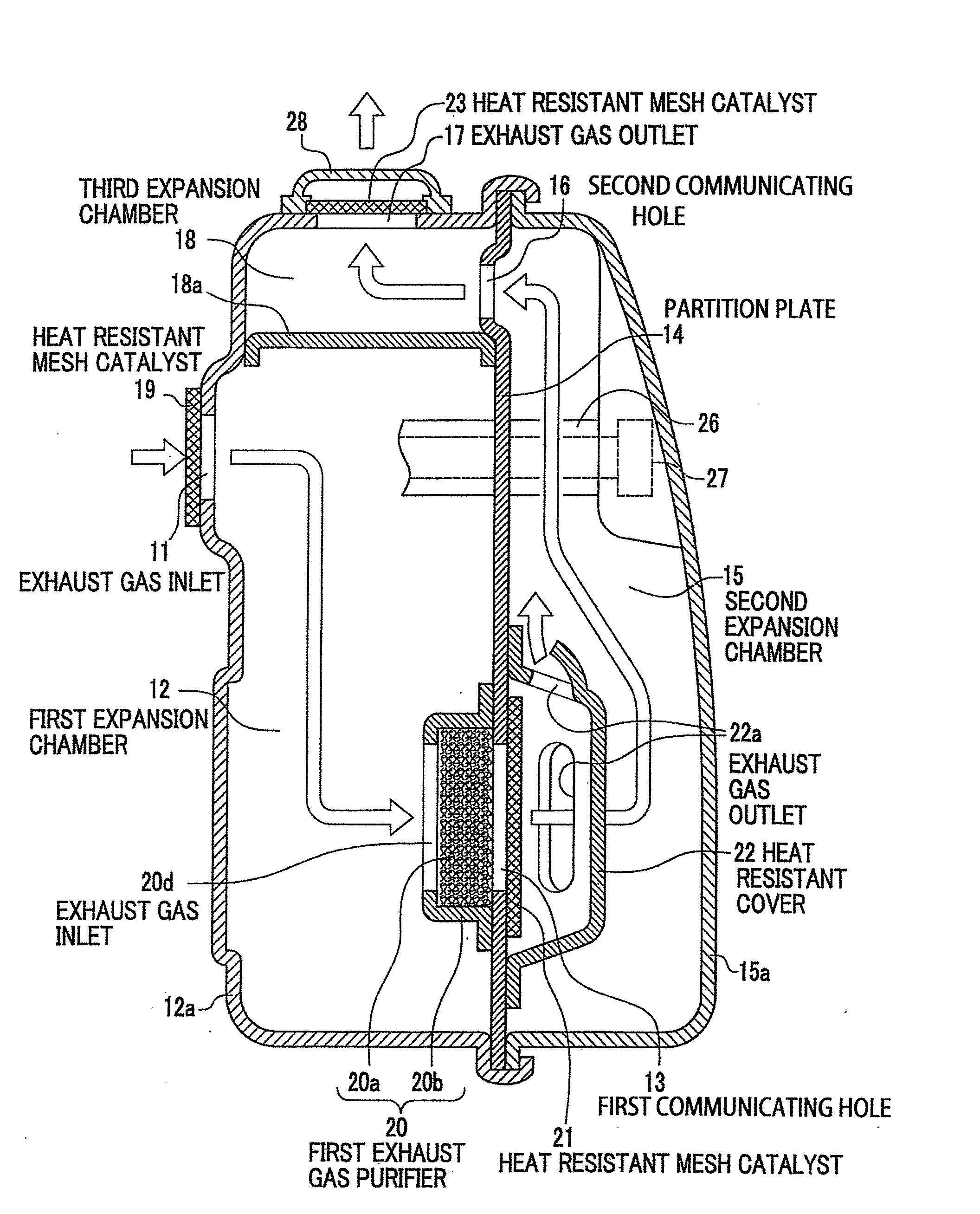
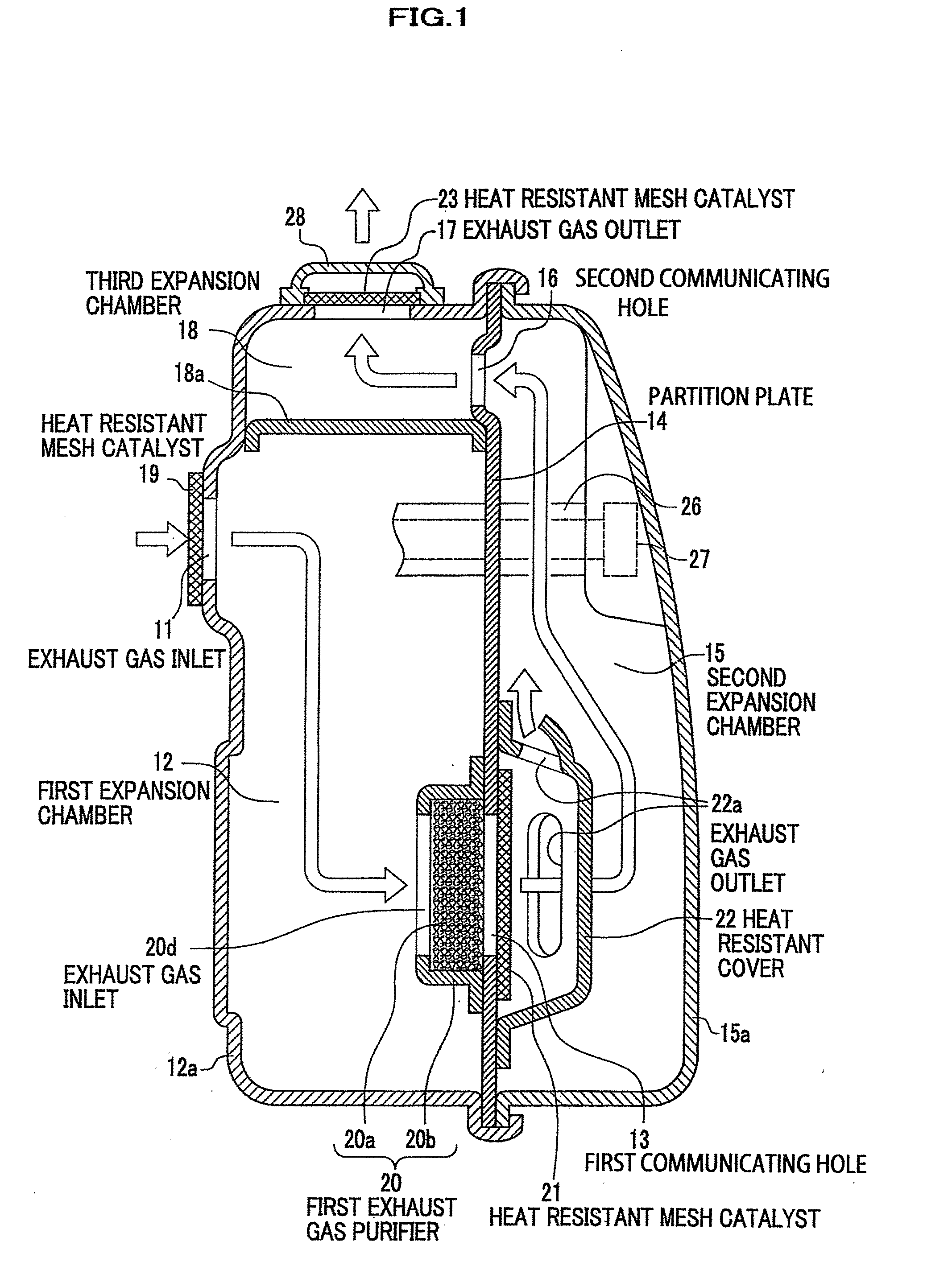
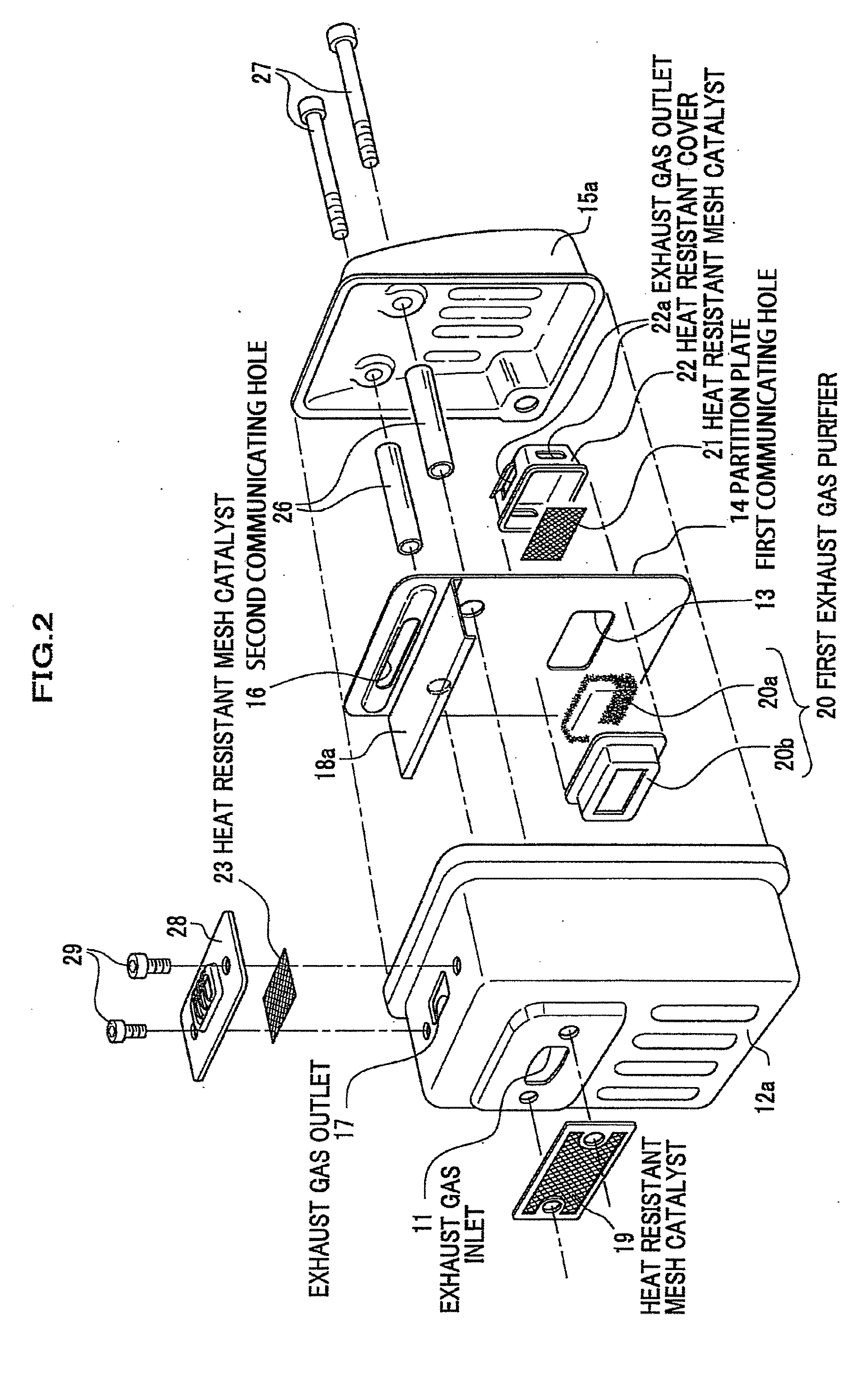
[0073]FIG. 1 is a cross-sectional view according to one embodiment of a muffler for a small engine of the present invention. FIG. 2 is an exploded perspective view thereof and FIG. 3 is an assembling perspective view thereof.

[0074]The muffler for a small engine according to the one embodiment of the present invention includes: a first expansion chamber 12 having an exhaust gas inlet 11 being connected to an exhaust gas outlet of the engine; a second expansion chamber 15 for exhaust gas partitioned from the first expansion chamber 12 by a partition plate 14 and communicated with the first expansion chamber 12 through a first communicating hole 13 on the partition plate 14; and a third expansion chamber 18 for the exhaust gas having an exhaust gas outlet 17, partitioned from the second expansion chamber 15 by the partition plate 14 and communicated with the second expa...


PUM


Abstract

A muffler for a small engine includes a first expansion chamber 12 for exhaust gas having an exhaust gas inlet 11 being connected to an exhaust gas outlet of the engine, a second expansion chamber 15 being partitioned from the first expansion chamber 12 by a partition plate 14 and being communicated with the first expansion chamber 12 through a first communicating hole 13 on the partition plate 14, and a third expansion chamber 18 being partitioned from the second expansion chamber 15 by the partition plate 14 and being communicated with the second expansion chamber 15 through a second communicating hole 16 on the partition plate 14 and having an exhaust gas outlet 17. A first heat resistant mesh catalyst 19 is disposed on the exhaust gas inlet 11. A first exhaust gas purifier 20 composed of a heat resistant knit fabric 20a coated with a catalyst for purifying the exhaust gas is disposed on the communicating hole 13 on the partition plate 14. Accordingly, the muffler for a small engine having a large muffling effect and a large purification effect on the exhaust gas can be provided. A manufacturing process of the exhaust gas purifier is simple and thereby a manufacturing cost of the muffler for a small engine is reduced.

Description

TECHNICAL FIELD[0001]The present invention relates to a muffler for a small engine suited for use in a brush cutter or a chain saw, for example.BACKGROUND ART[0002]A conventional muffler for a small engine comprises, as shown in FIG. 21, an exhaust gas first expansion chamber 2 having an exhaust gas inlet 1 connected to an exhaust gas outlet of the engine, and an exhaust gas second expansion chamber 4 having an exhaust gas outlet 3. Between the first expansion chamber 2 and the second expansion chamber 4, for example, an exhaust gas purifier 5 made of a honeycomb-like stainless steel support body having innumerable small holes along an axial direction and coated with a catalyst such as Rhodium, Palladium, etc., is disposed.[0003]Further, a conventional muffler for a small engine comprises, as shown in FIG. 22, an exhaust gas first expansion chamber 2 having an exhaust gas inlet 1 connected to an exhaust gas outlet of the engine and an exhaust gas second expansion chamber 4 having an...

Claims


Application Information

Patent Timeline
IPC IPC(8): F01N3/28F01N7/08F01N13/08
CPCF01N2590/06F01N1/089F01N1/165F01N3/05F01N3/2885F01N13/002Y02T10/20F01N13/141F01N2240/36F01N2330/12F01N2450/30F01N2470/30F01N13/14Y02T10/12
Inventor MUKAIDA, HIDENORI
Owner HIRAOKA MFG
Learn More