Particle beam device and method for use in a particle beam device

a particle beam and beam technology, applied in the direction of optical radiation measurement, machines/engines, instruments, etc., can solve the problems of complex construction and contamination of second specimens

Active Publication Date: 2009-01-15
CARL ZEISS MICROSCOPY GMBH
View PDF17 Cites 17 Cited by
  • Summary
  • Abstract
  • Description
  • Claims
  • Application Information

AI Technical Summary

Benefits of technology

[0010]The system described herein is based in particular on the idea that components already present in a particle beam device, in particular a specimen table designed as a carrier element and situated in such a way that it is movable, are usable for simplifying a device for specimen study and / or specimen preparation. In both particle beam devices described above, a specimen does not have to be discharged from a vacuum chamber for further study. In particular if two receiving elements are arranged, it is possible to extract a second specimen from a first specimen, and to prepare and study the second specimen, without the second specimen having to be discharged from a vacuum chamber. Furthermore, because of the configuration of the two receiving elements on the carrier element, simple and well-controllable movement sequences are possible. The entire process described above is executable completely automatically using a suitable controller. This is also true for the particle beam device according to the system described herein, in which, by the removal and subsequent reconnection of the receiving element, the receiving element may be brought into a position in which a specimen may be irradiated using a particle beam. The system described herein also has the advantage that the receiving element(s) do / does not have to have any movement mechanisms, because all required movements may be implemented via the degrees of freedom of the carrier element (e.g., a specimen table). The carrier element having the receiving element(s) is also particularly well suitable for discharging a specimen out of the particle beam device (for example, a specimen prepared in the particle beam device). Additionally or alternatively thereto, the carrier element having the receiving element(s) is particularly well suitable for inserting a pre-prepared specimen into the particle beam device.
[0025]Because of the particular design of the carrier element and the receiving element(s), the system described herein ensures sufficient free moving space in spite of possible restriction of the movement freedom of the carrier element (for example, a specimen table).

Problems solved by technology

This is disadvantageous for many applications, because the discharge of the specimen holder requires a long time on the one hand and, on the other hand, the danger exists that the second specimen may be contaminated.
However, this known device has the disadvantage that it has quite a complex construction.

Method used


Image

  • Particle beam device and method for use in a particle beam device
  • Particle beam device and method for use in a particle beam device
  • Particle beam device and method for use in a particle beam device

Examples


Embodiment Construction

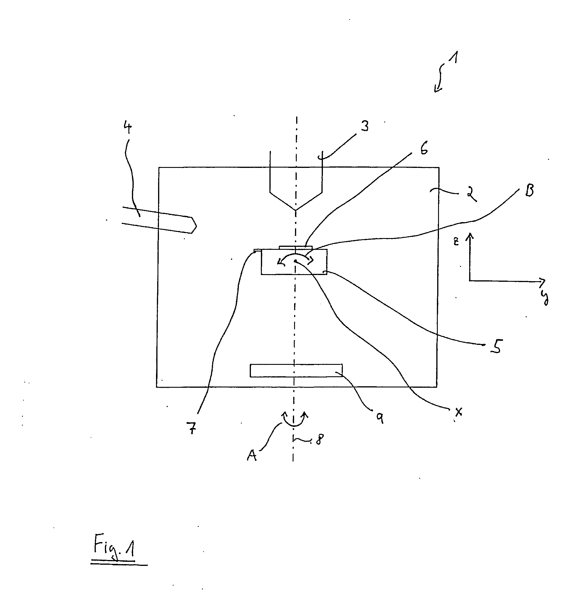
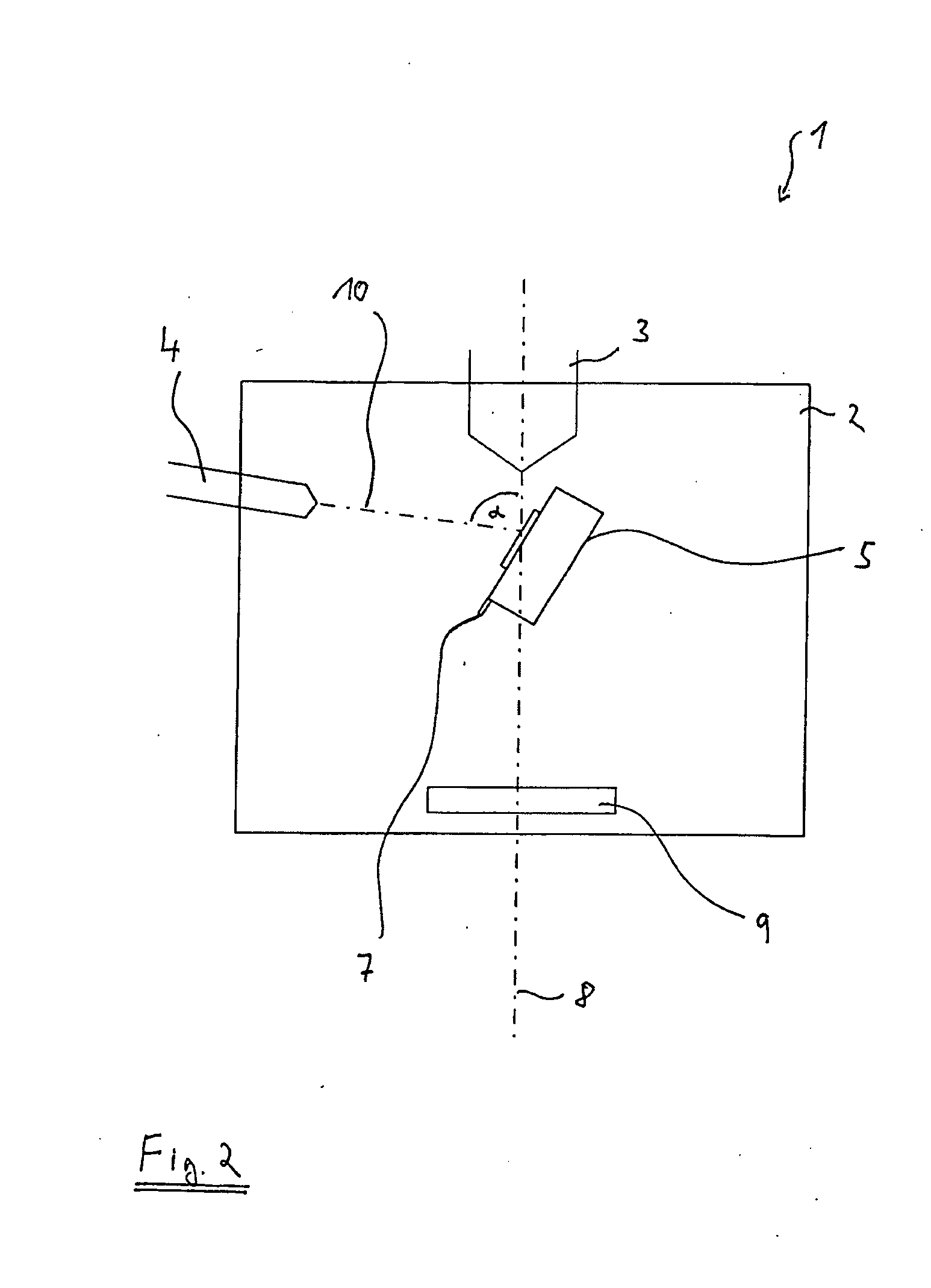
[0055]FIG. 1 shows a schematic illustration of a particle beam device 1 in the form of a scanning electron microscope, which is designed having an ion beam unit according to an embodiment of the system described herein. Therefore, both a first particle beam column 3 in the form of an electron column and also a second particle beam column 4 in the form of an ion column are situated on a vacuum chamber 2. The construction of individual particle beam columns 3 and 4 will be described in greater detail below.

[0056]Furthermore, a carrier element 5 in the form of a specimen table is situated in vacuum chamber 2. Carrier element 5 is designed movably in three spatial directions x, y, and z situated perpendicular to one another. Spatial directions z and y are shown laterally from vacuum chamber 2. Spatial direction x is perpendicular to the image plane. In addition, carrier element 5 is arranged in such a way that it is rotatable around an axis 8, which is indicated by arrow A. Axis 8 is si...


PUM

PropertyMeasurementUnit
angleaaaaaaaaaa
angleaaaaaaaaaa
angleaaaaaaaaaa

Abstract

A particle beam device includes a movable carrier element with at least one receiving element for receiving a specimen and in which the receiving element is situated on the carrier element. In various embodiments, the receiving element may be situated removably on the carrier element and / or multiple receiving elements may be situated on the carrier element in such a way that a movement of the carrier element causes a movement of the multiple receiving elements in the same spatial direction or around the same axis. The carrier element may be movable in three spatial directions situated perpendicular to one another and rotatable around a first axis which is parallel to an optical axis of the particle beam device and around a second axis which is situated perpendicular to the optical axis. A method for using the particle beam device in connection with specimen study and preparation is also disclosed.

Description

TECHNICAL FIELD[0001]This application relates to a particle beam device and a method for use in a particle beam device, in which a specimen is situated on a carrier element. This application also relates to a carrier element having a specimen receiving element.BACKGROUND OF THE INVENTION[0002]Particle beam devices, such as electron beam devices, have been used for some time for studying objects (specimens). In particular, scanning electron microscopes and transmission electron microscopes are known. In a scanning electron microscope, an electron beam generated using a beam generator is focused through an objective lens on the object to be studied. Using a deflection device, the electron beam (also referred to as the primary electron beam hereafter) is scanned over the surface of the object to be studied. The electrons of the primary electron beam interact with the object. As a result of the interaction, in particular electrons are emitted from the object (so-called secondary electro...

Claims


Application Information

Patent Timeline
Patent Type & Authority Applications(United States)
IPC IPC(8): G01N23/00
CPCH01J37/20H01J37/26H01J37/3056H01J2237/31749H01J2237/20207H01J2237/206H01J2237/31745H01J2237/201
Inventor ZEILE, ULRIKESCHERTEL, ANDREAS
Owner CARL ZEISS MICROSCOPY GMBH
Why Eureka
Try Eureka