
Control system architecture for qubits

a control system and qubit technology, applied in the field of quantum computing, can solve the problems of data loss or corruption in quantum computers, and the limitations of existing qubit implementations (such as by nmr) to achieve the effect of reducing the cost of qubits, and increasing the number of required qubits

Active Publication Date: 2009-01-15
IBM CORP
View PDF2 Cites 32 Cited by
  • Summary
  • Abstract
  • Description
  • Claims
  • Application Information

AI Technical Summary

Benefits of technology

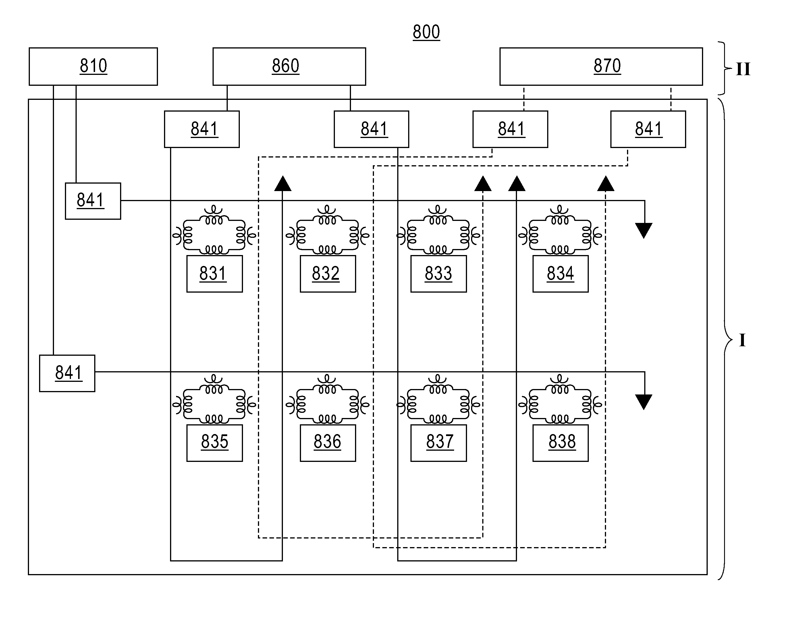
[0013]According to an exemplary embodiment of the present invention, a control system architecture for quantum computing includes an array of qubits, which is divided into a plurality of sub-arrays based on a first direction and a second direction, the second direction intersecting the first direction, a plurality of control lines each coupled to a corresponding sub-array of qubits in the first direction, a plurality of enable/unenable lines each coupled to a corresponding sub-array of qubits in the second direction, a control signal source that generates a control signal, wherein the control lines are used to apply the control signal commonly to one or more sub-arrays of qubits in the first direction, an enable signal source that generates a enable signal, wherein the enable/unenable lines are used to apply the enable signal independently to the corresponding sub-array of qubits in the second direction to set a bias point of each qubit of the corresponding sub-array of qubits in the second direction between a first position, in which the qubit is unenabled and not responsive to the control signal, and a second position, in which the qubit is enabled and responsive to the control signal.
[0014]According to an exemplary embodiment of the present invention, a method of controlling a qubit array includes generating a first signal to set a bias point of a plurality of qubits to a first positions in which each qubit is unenabled and not responsive to a control signal, generating a second signal to move the bias point of selected qubits from the first

Problems solved by technology

After successes with few-qubit systems, including demonstration of the Shor factorization algorithm with NMR (Nuclear Magnetic Resonance)-based techniques, existing qubit implementations (such as by NMR) have run into limitations of non-scalability.
Data loss or corruption can occur in a quantum computer due to interaction of qubits with particles in the environment causing changes in the qubit's quantum mechanical state.
However the use of quantum error correcting codes brings with it the cost of an increased number of required qubits.
However, to build a quantum computer capable of solving actual problems, for example, a quantum computer using 1,000,000 qubits, the number of wires running from the qubits working at 30 mK to room temperature becomes unmanageable.

Method used


Image

  • Control system architecture for qubits
  • Control system architecture for qubits
  • Control system architecture for qubits

Examples


Embodiment Construction

[0026]Hereinafter, exemplary embodiments of the present invention will be described with reference to the accompanying drawings. As used herein, the term “room temperature” refers to ambient or atmospheric temperature. In general, room temperature may be taken to be about 20° C. to about 25° C.

[0027]It is to be understood that exemplary embodiments of the present invention described herein may be implemented in various forms of hardware, software, firmware, special purpose processors, or a combination thereof. An exemplary embodiment of the present invention may take the form of an entirely hardware embodiment, an entirely software embodiment or an embodiment containing both hardware and software elements. An exemplary embodiment may be implemented in software as an application program tangibly embodied on one or more program storage devices, such as for example, computer hard disk drives, CD-ROM (compact disk-read only memory) drives and removable media such as CDs, DVDs (digital v...


PUM


Abstract

A control system architecture for quantum computing includes an array of qubits, which is divided into a plurality of sub-arrays based on a first direction and a second direction, the second direction intersecting the first direction, a plurality of control lines each coupled to a corresponding sub-array of qubits in the first directions a plurality of enable / unenable lines each coupled to a corresponding sub-array of qubits in the second direction, a controls signal source that generates a control signal, wherein the control lines are used to apply the control signal commonly to one or more sub-arrays of qubits in the first direction, an enable / unenable signal source that generates a enable signal, wherein the enable / unenable lines are used to apply the enable signal independently to the corresponding sub-array of qubits in the second direction to set a bias point of each qubit of the corresponding sub-array of qubits in the second direction between a first position, in which the qubit is unenabled and not responsive to the control signal, and a second position, in which the qubit is enabled and responsive to the control signal.

Description

BACKGROUND OF THE INVENTION[0001]1. Field of the Invention[0002]The present disclosure relates to quantum computing and, more particularly, to a control system architecture for controlling qubits.[0003]2. Description of Related Art[0004]A “quantum computer” is an apparatus for information processing or computation that uses the quantum mechanical state of a physical system to represent the logical state of the apparatus. Quantum computing is an interdisciplinary field of research that seeks to develop technologies that can harness the inherent capacity of quantum systems to do massively parallel processing of information. Considerable research effort has been directed toward developing quantum computers, given that ideal quantum computers have been shown to be capable of carrying out certain information processing tasks more rapidly than ordinary digital (classical) computers and have the potential to efficiently solve problems believed to be intractable on classical computers.[0005...

Claims


Application Information

Patent Timeline
IPC IPC(8): H03K17/92H01L39/22
CPCB82Y10/00H03K17/92G06N99/002G06N10/00
Inventor KOCH, ROGER HILSEN
Owner IBM CORP
Learn More