Device for producing electrical power in a two-spool gas turbine engine

a gas turbine engine and gas turbine technology, applied in the direction of machines/engines, efficient propulsion technologies, electric generator control, etc., can solve the problems of being somewhat heavy and definitely bulky, and allowing one of the electrical machines to drive the rotor, so as to limit the use of mechanical transmission components.

Active Publication Date: 2009-01-15
SN DETUDE & DE CONSTR DE MOTEURS DAVIATION S N E C M A
View PDF54 Cites 38 Cited by
  • Summary
  • Abstract
  • Description
  • Claims
  • Application Information

AI Technical Summary

Benefits of technology

[0012]The solution according to the invention has the advantage of allowing the tapping of mechanical power to be split between the two rotary spools without the need to resort to a clutch or gearbox system that would have an impact on the mass of the turbine engine.
[0013]Furthermore, the operability of the turbine engine is ensured by the fact that the split in the way in which power is tapped off is consistent between the two rotary spools. This split is controlled by suitable reduction ratios.
[0014]In the case of a two-spool engine, it has been demonstrated that tapping power from the LP spool in preference over any other spool allowed a reduction in the specific fuel consumption of a turbine engine.
[0018]However, a brake such as this is not needed when the ratio between the moments of inertia of the HP and LP spools is very great, as is the case with large engines.
[0019]Advantageously, the first rotor of the electrical machine is concentric with and inside the second rotor thereof. As a preference, the first rotor is a permanent magnet rotor; this then reduces the amount of contact between stationary and rotating parts.
[0022]This arrangement makes it possible to apply a gas turbine engine startup method that consists in powering the auxiliary electrical machine with electrical power while at the same time keeping the brake applied so as to drive the second rotary spool only during the startup phase.

Problems solved by technology

A solution such as this does have the disadvantage of being somewhat heavy and definitely bulky.
It will be noted that a solution such as this does not allow one of the electrical machines to drive the rotors on startup.

Method used


Image

  • Device for producing electrical power in a two-spool gas turbine engine
  • Device for producing electrical power in a two-spool gas turbine engine
  • Device for producing electrical power in a two-spool gas turbine engine

Examples


Embodiment Construction

[0032]Given these background considerations, the way in which the machine is arranged with respect to the rotary spools of the engine can vary.

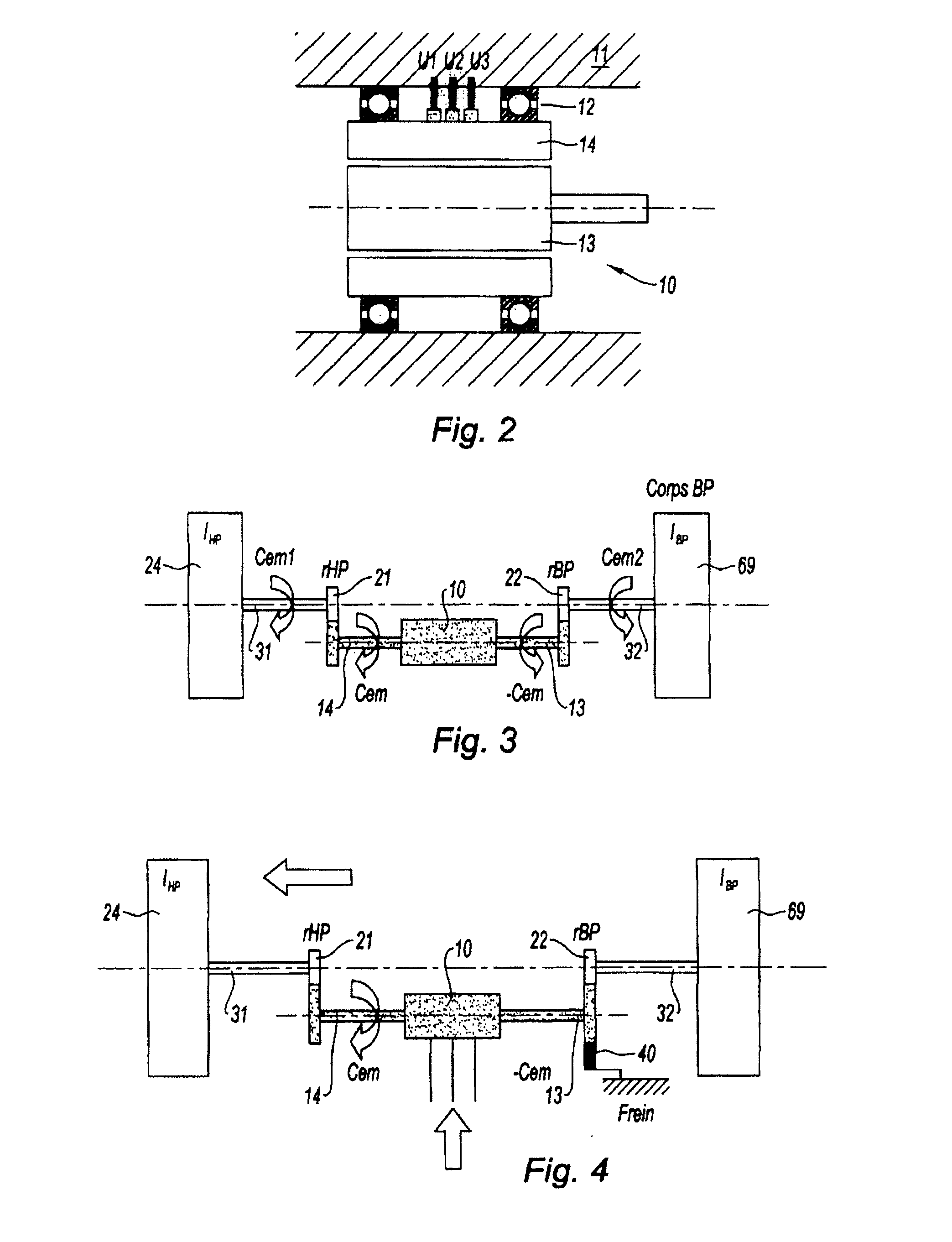
[0033]According to one embodiment, the electrical machine is positioned along or near the axis of the gas turbine engine. The first rotor 13 is then advantageously connected to the LP spool 69 and the second rotor 14 is connected to the HP spool 24. In order to allow drive at appropriate speeds for the electrical machine 10, its two rotors are connected to the two rotary spools by appropriate speed reducing gearboxes. FIG. 3 depicts the operating diagram of this arrangement. The electrical machine 10 is shown with the two shafts of the rotors 13 and 14. These two shafts 13 and 14 are connected by respective HP and LP reduction gearboxes 21 and 22 to the shafts 31 and 32 of the HP and LP spools 24 and 69 respectively. In this example, the two spools of the gas turbine engine are contrarotating with appropriate reduction gearboxes. The solution...


PUM


Abstract

The invention relates to a device for producing electrical power in a multi-spool gas turbine engine comprising at least one first rotary spool (69), for example a low-pressure spool, and a second rotary spool (24), for example a high-pressure spool, and driving an electrical machine (10). The device is one wherein, with the electrical machine (10) being of the twin-rotor type with a first rotor (13) and a second rotor (14), the first rotor (13) is mechanically connected to the first rotary spool (69) and the second rotor is mechanically connected to the second rotary spool (24).

Description

BACKGROUND OF THE INVENTION [0001]The present invention relates to the field of multi-spool gas turbine engines used in aeronautics. It is aimed at the way in which auxiliary electrical machines are driven by the shafts of the engine.[0002]In turbine engines used for the propulsion of aircraft, some of the power produced is tapped off to drive auxiliary equipment providing ancillary services both to the engines themselves and to the aircraft. This equipment includes the lubricating and fuel systems, and the power supply for the hydraulic and electrical systems.[0003]A multi-spool gas turbine engine comprises at least two rotary spools; most have two or three spools, but a higher number is not excluded. A spool consists of a unitary assembly rotating about an axis, with one section forming a compressor and one section forming a turbine, the latter driving the compressor. More specifically, a multi-spool engine may also be a multi-flow engine, generally a dual flow or bypass engine, ...

Claims


Application Information

Patent Timeline
Patent Type & Authority Applications(United States)
IPC IPC(8): F02C6/00
CPCF01D15/10F02C7/32H02K7/14F05D2260/90H02K16/005F05D2260/85H02K7/1823Y02T50/60
Inventor COLIN, ANTOINE OLIVIER FRANCOISLEBRUN, ARNAUDBARJON, GILLES
Owner SN DETUDE & DE CONSTR DE MOTEURS DAVIATION S N E C M A
Why Eureka
Try Eureka