Light guide place and light-diffusing structure thereof

a technology of light guide plate and light guide plate, which is applied in the direction of planar/plate-like light guide, lighting and heating apparatus, instruments, etc., can solve the problems of limited light diffusing capability of conventional v-shaped structure or arc-shaped structure b>120/b>, unfavorable hand-held electronic devices, and unfavorable linear light source such as cold cathode fluorescent lamps (ccfl), etc., to achieve better light diffusing distance of effectiv

Inactive Publication Date: 2009-01-15
WINTEK CORP
View PDF11 Cites 80 Cited by
  • Summary
  • Abstract
  • Description
  • Claims
  • Application Information

AI Technical Summary

Benefits of technology

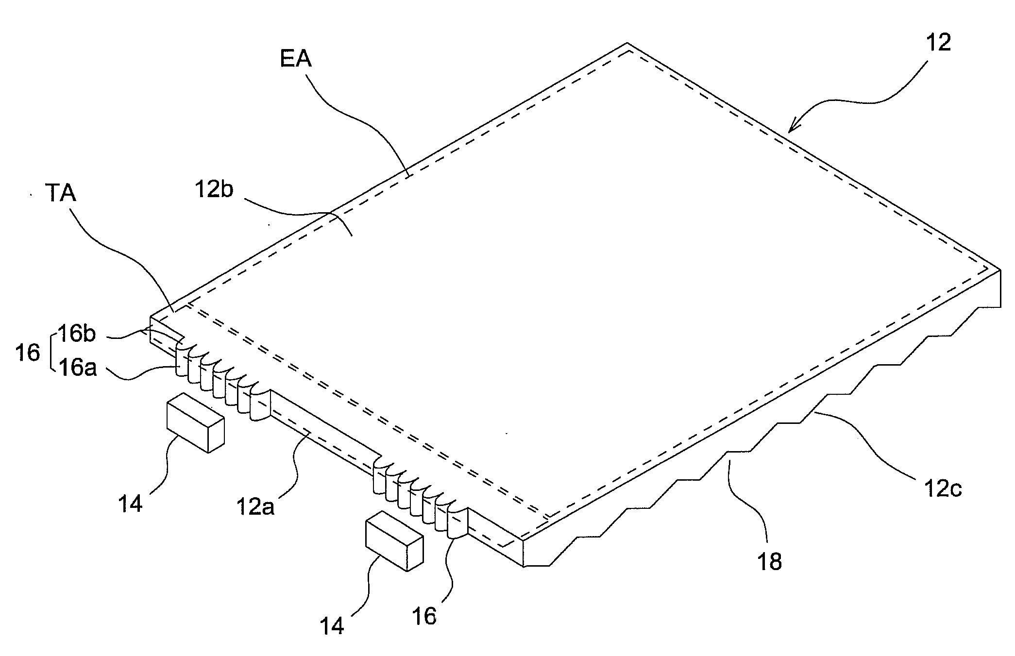
[0011]According to the above embodiments, the geometrical profile of the elliptic cylindrical surface allows for comparatively large light deflecting distances; that is, the elliptical light-diffusing structure has better light-diffusing capability. Thus, the distance between the point light source and the effective section can be shortened, with the brightness uniformity still being accepted, to increase the area of the effective secti

Problems solved by technology

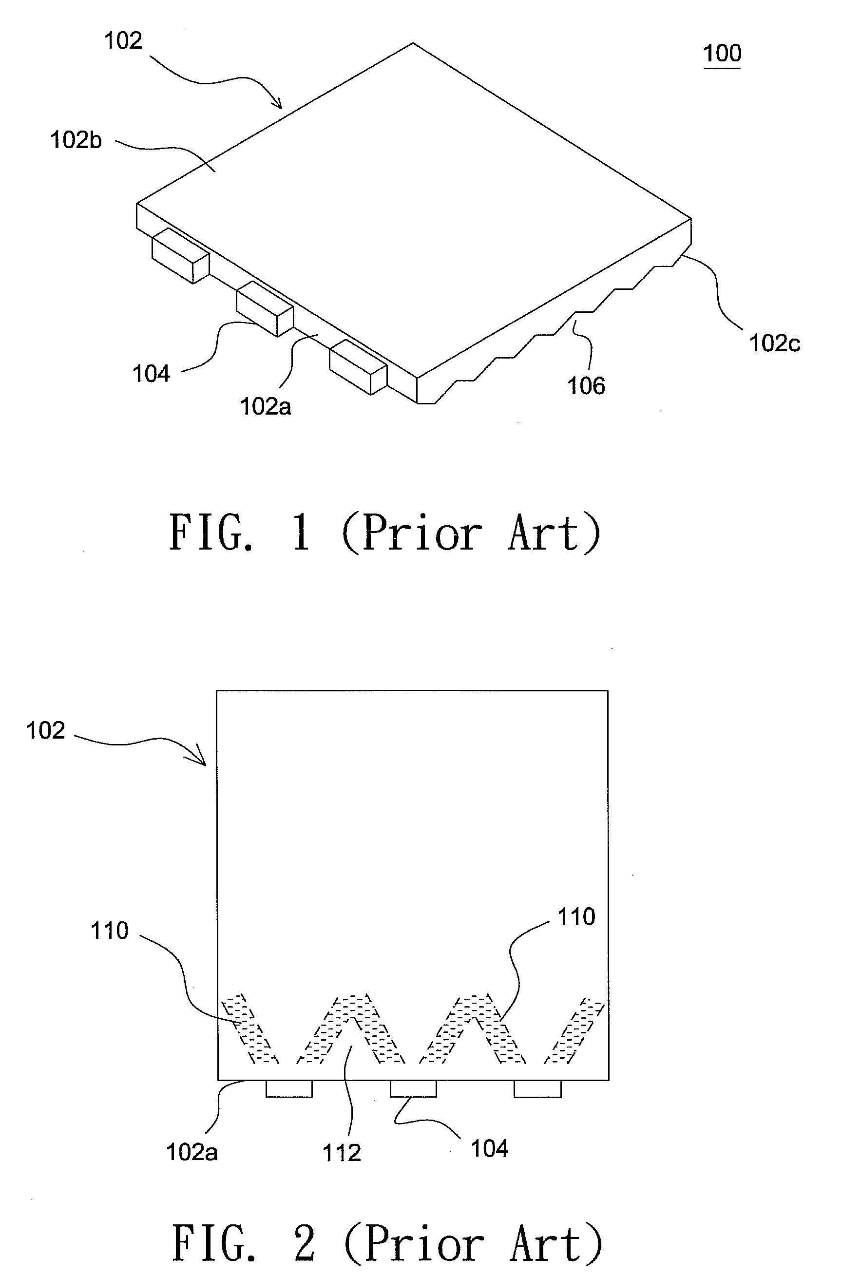
Generally, a linear light source, such as a cold cathode fluorescent lamp (CCFL) is not favorable for hand-held electronic devices due to its bulkiness.
This tends to result in uneven brightness of the light guide plate 102.
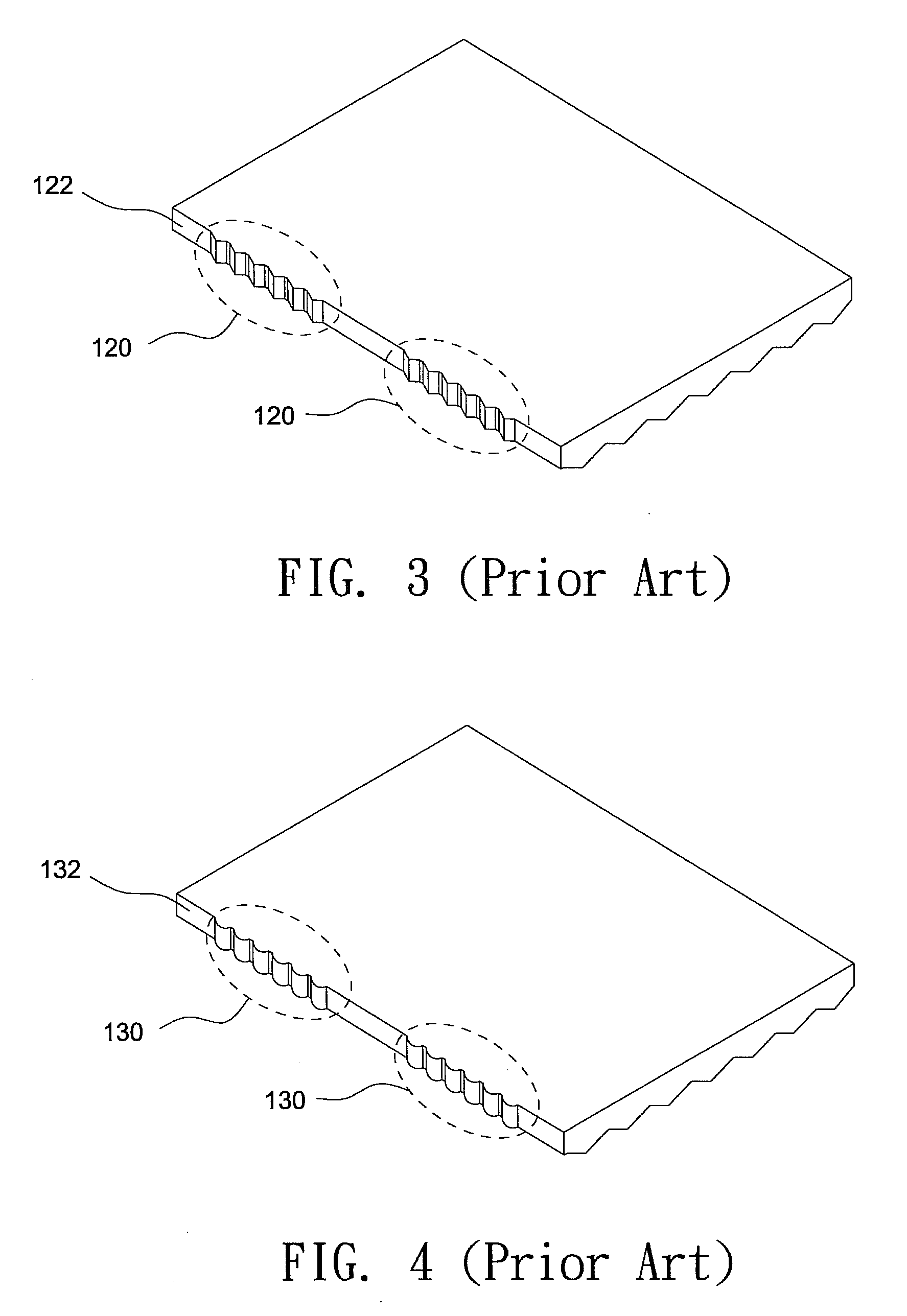
However, the conventional V-shaped structur

Method used


Image

  • Light guide place and light-diffusing structure thereof
  • Light guide place and light-diffusing structure thereof
  • Light guide place and light-diffusing structure thereof

Examples


Embodiment Construction

[0040]In the following detailed description of the preferred embodiments, reference is made to the accompanying drawings which form a part hereof, and in which is shown by way of illustration specific embodiments in which the invention may be practiced. In this regard, directional terminology is used with reference to the orientation of the Figure(s) being described. The components of the present invention can be positioned in a number of different orientations. As such, the directional terminology is used for purposes of illustration and is in no way limiting. On the other hand, the drawings are only schematic and the sizes of components may be exaggerated for clarity. It is to be understood that other embodiments may be utilized and structural changes may be made without departing from the scope of the present invention. Also, it is to be understood that the phraseology and terminology used herein are for the purpose of description and should not be regarded as limiting. The use o...


PUM


Abstract

A light guide plate that is divided into an effective section capable of providing uniform surface illumination and a transitional section between the effective section and the point light source includes a light-receiving surface, a light-emitting surface, a light-reflecting surface, and a plurality of light-diffusing structures. The light-diffusing structures are spread on the transitional section, and each light-diffusing structure is in the shape of a part elliptic cylinder having a long axis and a short axis and the front surface of the light-diffusing structure facing the point light source is a part elliptic cylindrical surface.

Description

CROSS REFERENCE TO RELATED APPLICATION[0001]This application claims priority of applications No. 096125382 and No. 096136697 filed in Taiwan R.O.C on Jul. 12, 2007 and Oct. 1, 2007, respectively, under 35 U.S.C. § 119; the entire contents of which are hereby incorporated by reference.BACKGROUND OF THE INVENTION[0002]1. Field of the Invention[0003]The invention relates to a light-diffusing structure with excellent light diffusing effect and a light guide plate having enhanced luminous uniformity and light utilization efficiency.[0004]2. Description of the Related Art[0005]Generally, a linear light source, such as a cold cathode fluorescent lamp (CCFL) is not favorable for hand-held electronic devices due to its bulkiness. Instead, a point light source is typically used in a hand-held electronic device like a mobile phone and serves as the side light source for an LCD panel incorporated therein. FIG. 1 shows a schematic diagram illustrating a conventional backlight module 100. As show...

Claims


Application Information

Patent Timeline
IPC IPC(8): G02F1/13357F21V8/00
CPCG02B6/002G02B6/0015
Inventor YE, ZHI-TING
Owner WINTEK CORP
Why Eureka
Try Eureka