Thermally Switched Reflective Optical Shutter

a reflective optical shutter and thermal switch technology, applied in the direction of optical elements, door/window protective devices, instruments, etc., can solve the problems of limiting the utility of the system in temperature-regulating applications, affecting the ability of the system to regulate temperature, and blocking unwanted sunlight in cold weather and unwanted sunligh

Inactive Publication Date: 2009-01-15
RAVENBRICK
View PDF44 Cites 167 Cited by
  • Summary
  • Abstract
  • Description
  • Claims
  • Application Information

AI Technical Summary

Problems solved by technology

However, because they are controlled by UV light rather than by temperature, such systems are of limited utility in temperature-regulating applications.
For example, they may block wanted sunlight in cold weather as well as unwanted sunlight in hot weather.
These liquid crystal panels are typically used in video displays, which are designed to not be isotropic under operating conditions and have seen only very limited use in building materials.
The heat absorbed by these materials may also offset the reductions in radiative transmission, and thus place significant limits on their ability to regulate temperature.
These switchable mirrors rely on the physical migration of ions across a barrier under the influence of an electric field and therefore have limited switching speeds and cycle lifetimes. In addition, electrically operated “light valves” combine liquid crystals with one or more reflective polarizers as described, for example, in U.S. Pat. No. 6,486,997 to Bruzzone, et al.

Method used


Image

  • Thermally Switched Reflective Optical Shutter
  • Thermally Switched Reflective Optical Shutter
  • Thermally Switched Reflective Optical Shutter

Examples


Embodiment Construction

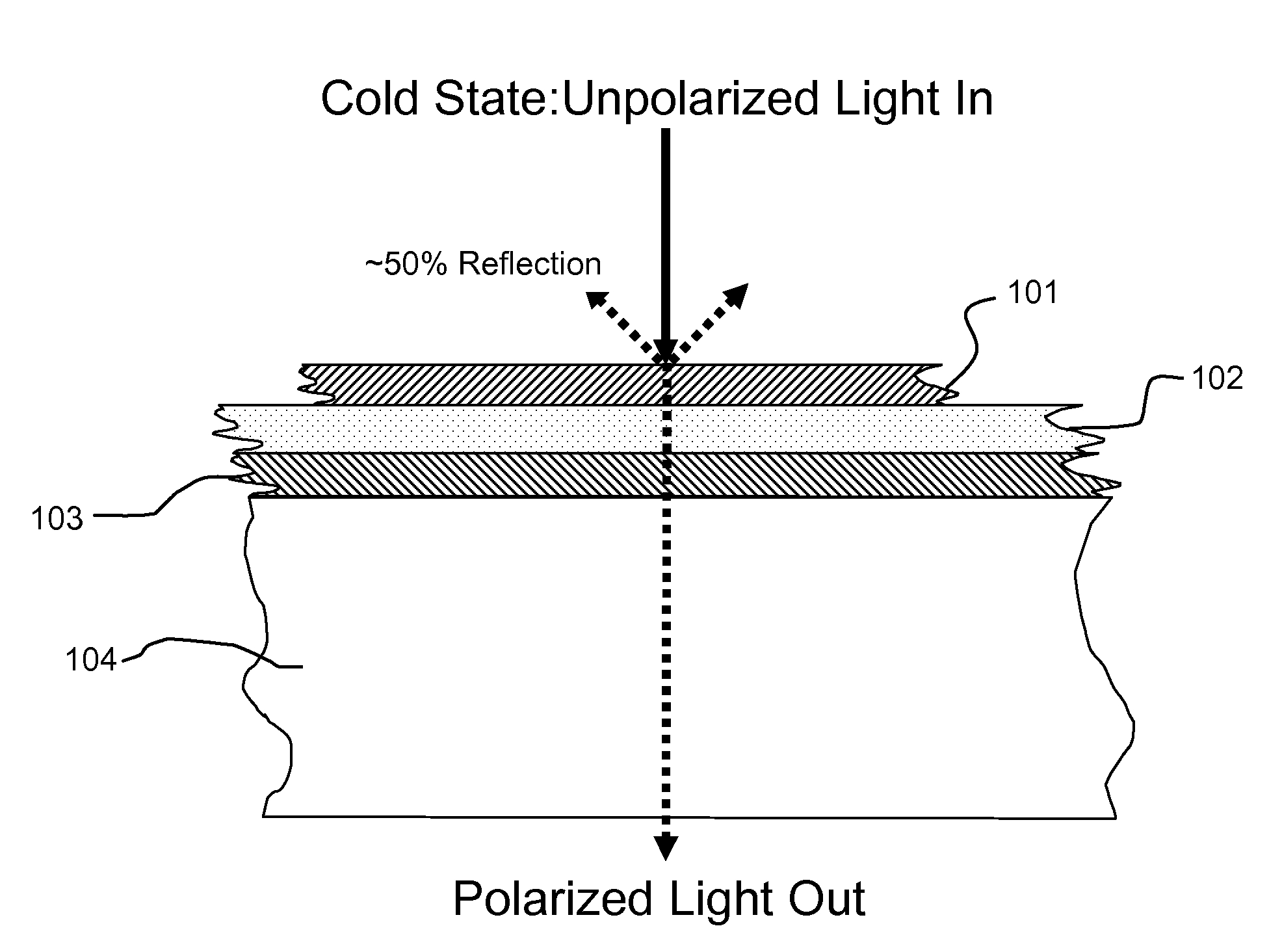
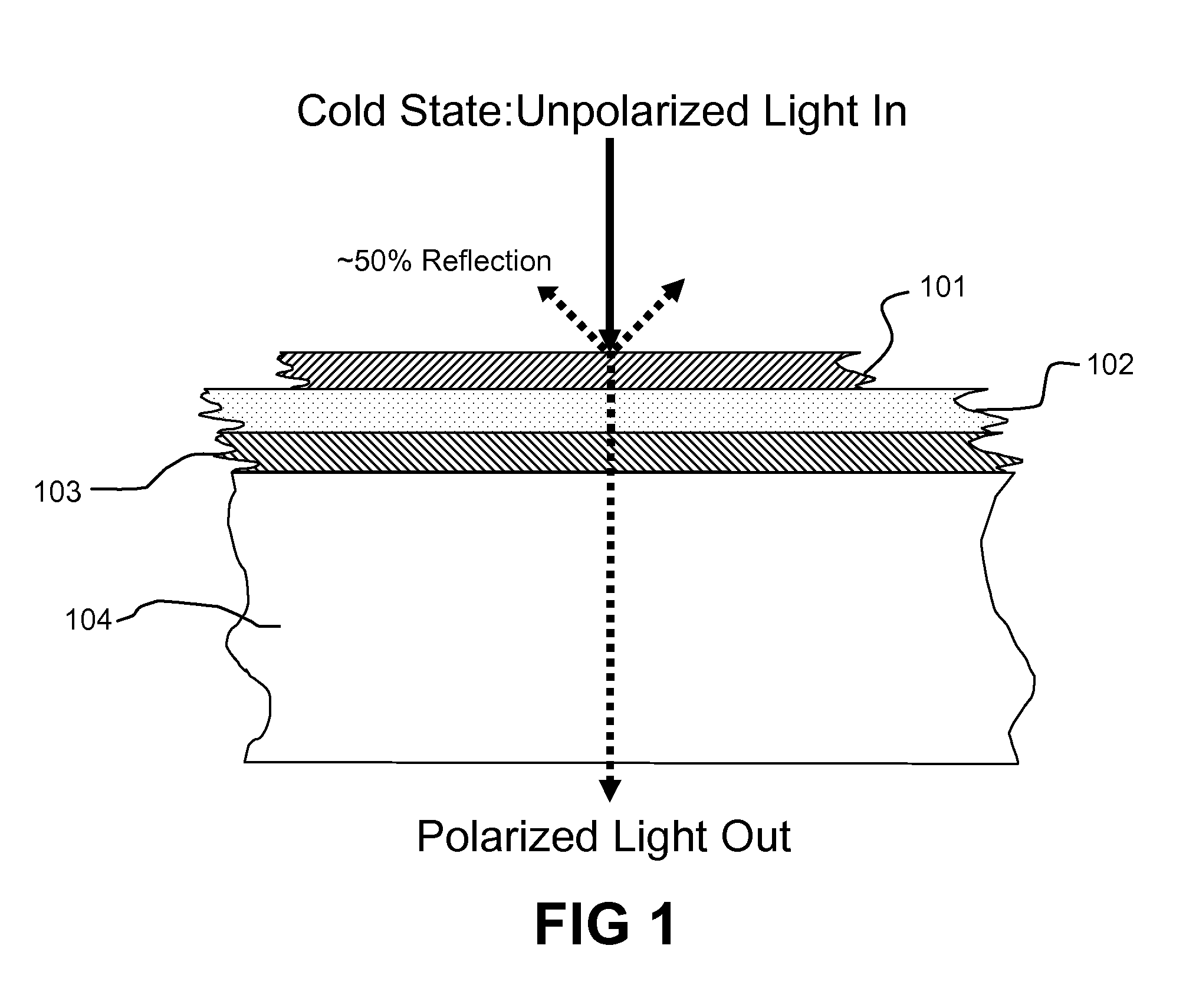
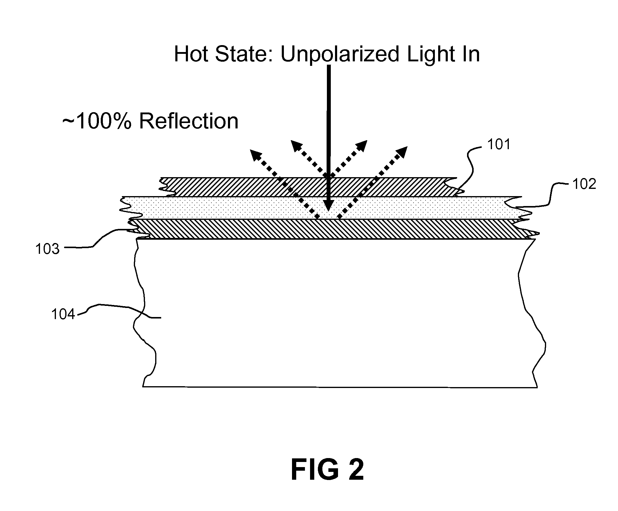
[0030]A thermotropic optical depolarizer may be used in conjunction with two reflective polarizers to create a thermally switched reflective optical shutter (TSROS) that allows light and radiant energy to pass through the shutter at low temperatures and reflects it away at high temperatures. The depolarizer is specifically selected or designed to be thermotropic, i.e., its polarization state shifts at a predetermined temperature. The TSROS device has particular, but not exclusive, application in regulating the temperatures of buildings, vehicles, or other structures by controlling the amount of solar radiation they absorb.

[0031]The structure, composition, manufacture, and function of liquid crystals, polarizers, and reflective polarizers are well documented, but the following elaboration is presented for better understanding. Many materials exhibit thermotropic properties, including liquid crystals, which transition from an ordered or “ON” state (e.g., crystalline, nematic, or smect...


PUM

PropertyMeasurementUnit
clearing pointaaaaaaaaaa
angleaaaaaaaaaa

Abstract

The thermally switched reflective optical shutter is a self-regulating “switchable mirror” device that reflects up to 100% of incident radiant energy above a threshold temperature, and reflects up to 50% of incident radiant energy below a threshold temperature. Control over the flow of radiant energy occurs independently of the thermal conductivity or insulating value of the device, and may or may not preserve the image and color properties of incoming visible light. The device can be used as a construction material to efficiently regulate the internal temperature and illumination of buildings, vehicles, and other structures without the need for an external power supply or operator signals. The device has unique aesthetic optical properties that are not found in traditional windows, skylights, stained glass, light fixtures, glass blocks, bricks, or walls. The device can be tailored to transmit sufficient visible light to see through in both the transparent and reflective states, while still providing significant control over the total energy transmission across the device.

Description

CROSS REFERENCE TO RELATED APPLICATIONS[0001]This application is entitled to the benefit of priority pursuant to 35 U.S.C. §119(e) of U.S. provisional patent application No. 60 / 959,096 filed 11 Jul. 2007 entitled “Thermally switched reflective optical shutter,” which is hereby incorporated by reference herein in its entirety.BACKGROUND[0002]1. Technical Field[0003]The subject matter described herein relates to a device for controlling the flow of light and radiant heat through selective reflection. The technology has particular, but not exclusive, application in passive or active light-regulating and temperature-regulating films, materials and devices, especially as construction materials.[0004]2. Description of the Related Art[0005]The problem of controlling the flow of radiant energy, e.g., light and heat, in particular in applications such as regulating solar heat gain in buildings and in other applications has previously been addressed using many optical methodologies. Photodark...

Claims


Application Information

Patent Timeline
Patent Type & Authority Applications(United States)
IPC IPC(8): G02F1/19G02F1/1333
CPCE06B9/24E06B2009/2464G02B27/28G02F1/0147G02F1/132G02F2001/0139G02F1/133533G02F1/133536G02F2001/133538G02F1/0136G02F1/133514G02F1/133538G02F1/0139
Inventor POWERS, RICHARD M.MCCARTHY, WIL
Owner RAVENBRICK
Why Eureka
Try Eureka