Zoom lens employing lens eccentricity approach to compensate for image blur due to hand tremor

a zoom lens and eccentricity technology, applied in the field of high magnification power zoom lenses, can solve the problems of insufficient space for insufficient space for the attachment of the actuator around the aperture, and insufficient space for the eccentric movement of the lens elemen

Inactive Publication Date: 2009-01-15
TAMRON
View PDF1 Cites 5 Cited by
  • Summary
  • Abstract
  • Description
  • Claims
  • Application Information

AI Technical Summary

Benefits of technology

[0025]The zoom lens according to the present invention can have its lens element abaxially deviated as much as 0.5 mm to 1 mm in the telephoto view mode without deteriorating the imaging precision so much as it is not to fit to be used in practice, and such a lens eccentricity approach is effective in compensating for an image blur due to the hand tremor.
[0026]Further, the zoom lens according to the present invention has an anti-hand-tremor feature that is based on an abaxial deviation of a lens element, and the lens element to eccentrically move is located apart from an aperture stop so that there is a sufficient space to attach an actuator for the lens element and a shutter-driving device.
[0027]Moreover, in the zoom lens according to the present invention, part of a lens group, which is immediately behind another lens group with an aperture stop located therein (i.e., right on the rear side of the lens group, closer to an image plane), is eccentrically moved from the remaining lens groups to compensate for an image blur caused by the hand tremor, resulting in ensuring a space available to attach a shutter-driving motor around the aperture stop and ensuring a sufficient adaxial clearance filled with air on either the eyepiece side or the nosepiece side of a lens element to deviate in an abaxial manner so that there is a sufficient space to attach an actuator to eccentrically move the lens element.
[0028]Furthermore, in the zoom lens according to the present invention, a lens element to eccentrically move to avoid an image blur caused by the hand tremor is a composite lens of more than one lens elements cemented together, so that an abaxial deviation of the lens element would not cause significant chromatic aberration of magnification, and that a zooming ratio can be raised to be suitable for the close-up photographing in the telephoto view mode.<Description of the Requirements for the Optics Design>

Problems solved by technology

A high magnification power zoom lens as disclosed in the Patent Document 1, which is approximately 75 degrees in photo-shooting coverage angle in the prior art wide-angle view mode and as high as 10× in magnification power ratio, is structurally unsatisfactory to deviate a lens element in an abaxial manner and compensate for an image blur caused by the hand tremor.
In a lens optics as disclosed in the Patent Documents 2 and 3 that has an anti-hand-tremor feature, a lens element to eccentrically move for regulating the imaging is located in the vicinity of an aperture stop, and there is not a sufficient space to attach a lens actuator and a shutter-driving device around the aperture stop.
The zoom lens, although it ensures a sufficient space to attach a shutter-driving motor around an aperture stop, still provides an insufficient adaxial clearance filled with air on either the eyepiece side or the nosepiece side of a lens element to deviate in an abaxial manner, resulting in no sufficient space available for an attachment of an actuator to eccentrically move the lens element.
Further, in the zoom lens with an anti-hand-tremor feature as disclosed in the Patent Document 4, the lens element to eccentrically move to avoid an image blur caused by the hand tremor is not a composite lens of more than one lens elements cemented together, and therefore, an abaxial deviation of the lens element causes significant chromatic aberration of magnification.
For this reason, this approach is not suitable for the close-up photographing in the telephoto view mode.

Method used


Image

  • Zoom lens employing lens eccentricity approach to compensate for image blur due to hand tremor
  • Zoom lens employing lens eccentricity approach to compensate for image blur due to hand tremor
  • Zoom lens employing lens eccentricity approach to compensate for image blur due to hand tremor

Examples


embodiment 1

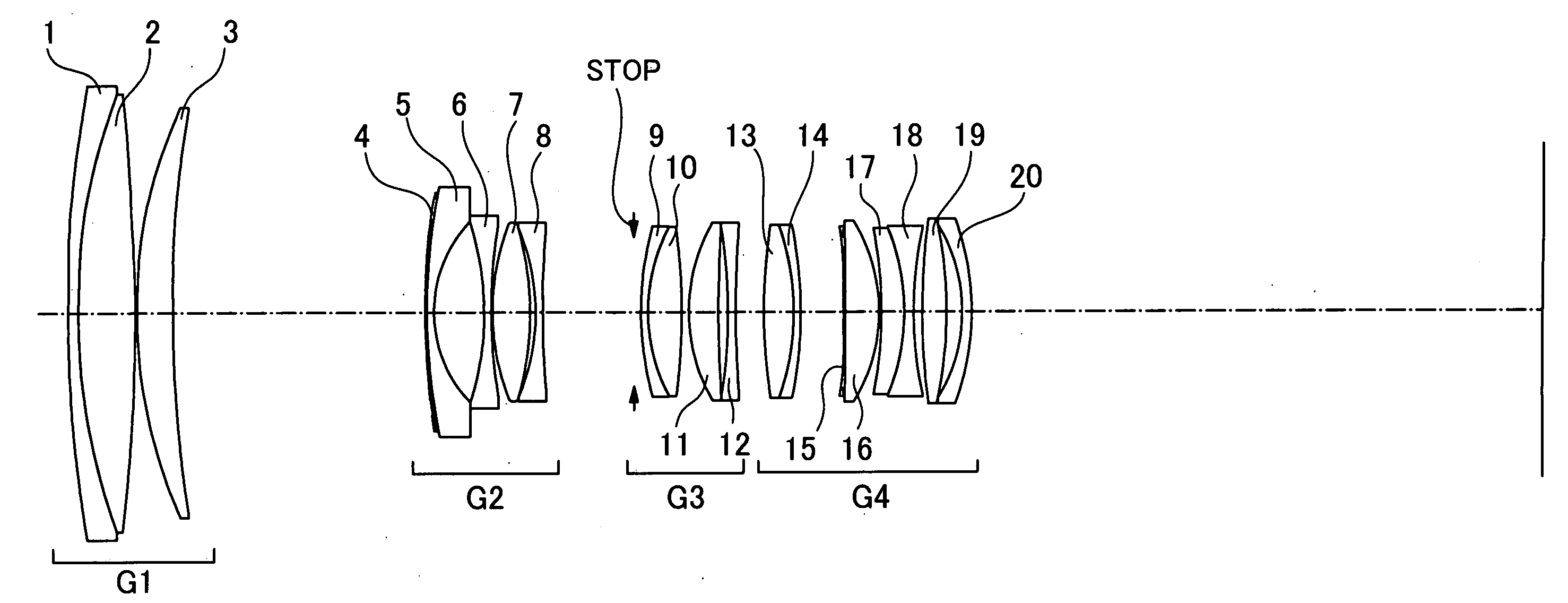
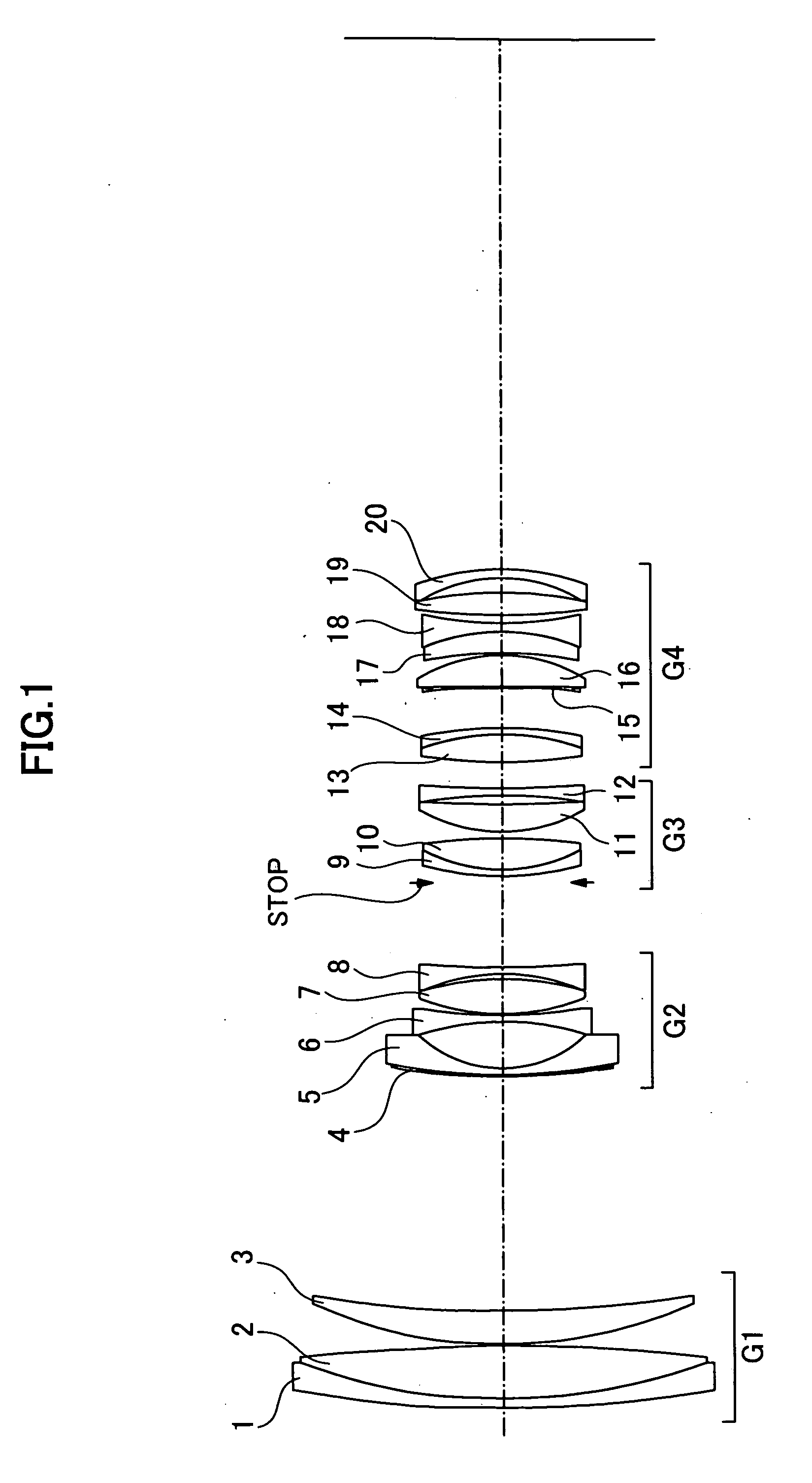
[0049]As cross-sectionally shown in FIG. 1, an embodiment of a zoom lens of the present invention, which employs a lens eccentricity approach to compensate for an image blur due to a tremor of the hand of a photographer, is comprised of twenty lens pieces, namely, the 1st lens element 1 to the 20th lens element 20. They work in four groups, namely, the 1st lens group to the 4th lens group, and the 1st lens group G1 has the 1st lens element 1 to the 3rd lens element 3. The 2nd lens group G2 has the 4th lens element 4 to the 8th lens element 8. The 3rd lens group G3 has the 9th lens element 9 to the 12th lens element 12. The 4th lens group G4 has the 13th lens element 13 to the 20th lens element 20. The 13th lens element 13 and the 14th lens element 14 in the lens group G4 are cemented together into a single composite lens that is to be eccentrically moved from the remaining lens pieces for the antitremor compensation.

[0050]In the following lookup table, f is a focal length (mm), Fno ...

embodiment 2

[0076]As cross-sectionally shown in FIG. 81, another embodiment of the zoom lens of the present invention, which employs a lens eccentricity approach to compensate for an image blur due to a tremor of the hand of a photographer, is comprised of twenty lens pieces, namely, the 1st lens element 101 to the 20th lens element 120. They work in four groups, namely, the 1st lens group to the 4th lens group, and the 1st lens group G1 has the 1st lens element 101 to the 3rd lens element 103. The 2nd lens group G2 has the 4th lens element 104 to the 8th lens element 108. The 3rd lens group G3 has the 9th lens element 109 to the 12th lens element 112. The 4th lens group G4 has the 13th lens element 113 to the 20th lens element 120. The 13th lens element 113 and the 14th lens element 114 in the 4th lens group G4 are cemented together into a single composite lens that is to be eccentrically moved from the remaining lens pieces for the anti-tremor compensation.

[0077]The following lookup table (Ta...


PUM


Abstract

Zoom lens, using lens eccentricity to compensate for image blur, has four groups of lens pieces; 1st, 3rd and 4th, each with positive refractive power, and 2nd with negative refractive power, arranged in series on “closer to a subject first” basis. Moving from wide to telephoto causes 1st and 2nd groups to separate from each other, 2nd and 3rd groups to come closer to each other, and 3rd and 4th groups to come closer to each other. The leading subset of the 4th group is closest to the subject, includes lens elements of positive and negative refractive power cemented together, and serves as an anti-tremor shift lens. The zoom lens satisfies the follows:1.45<f41 / fw<1.8where f41 is a focal length of the leading subset in the 4th lens group, and fw is a focal length of the lens optics as a whole in the wide-angle mode.

Description

FIELD OF THE INVENTION[0001]The present invention relates to a high magnification power zoom lens that is used for single-lens reflex cameras, digital cameras, and the like, and that deviate a lens element in an abaxial manner to compensate for an image blur due to a tremor of the hand of a photographer. More particularly, the present invention relates to a compact, light-weight, and high magnification power zoom lens that is more than 75 degrees in coverage angle, approximately 6 to 7 in F number in the telephoto view mode, and approximately 10× in magnification power, and that is capable of compensating for an image blue caused by a tremor of the photographer's hand.[0002]Drastic development and advancement of the optical design technology and the optics manufacturing technology for recent years have accelerated downsizing and enhancement of magnification power of zoom lenses. Some types of the zoom lenses, which incorporate four groups of lens elements that exert positive, negati...

Claims


Application Information

Patent Timeline
Patent Type & Authority Applications(United States)
IPC IPC(8): G02B15/14
CPCG02B27/646G02B15/173G02B15/144113
Inventor MURAMATSU, YUICHI
Owner TAMRON
Why Eureka
Try Eureka