Passive Q switch laser device

a laser device and q switch technology, applied in wave amplification devices, laser details, electrical devices, etc., can solve the problems of laser oscillation and pulse light generation, and achieve the effect of limiting the reduction of peak intensity

Active Publication Date: 2009-01-15
INTER UNIV RES INST NAT INST OF NATURAL SCI +1
View PDF1 Cites 17 Cited by
  • Summary
  • Abstract
  • Description
  • Claims
  • Application Information

AI Technical Summary

Benefits of technology

[0020]In accordance with the passively Q-switched laser apparatus according to the present invention, it is possible to achieve size reduction as well as to output pulse laser beams having a stabilized polarization direction while limiting the reduction in peak intensity.

Problems solved by technology

At this time, the Q-value of the optical resonator increases drastically to result in a laser oscillation and thereby generating pulse light.

Method used


Image

  • Passive Q switch laser device
  • Passive Q switch laser device
  • Passive Q switch laser device

Examples


Embodiment Construction

[0047]Preferred embodiments of a passively Q-switched laser apparatus according to the present invention will hereinafter be described with reference to the accompanying drawings.

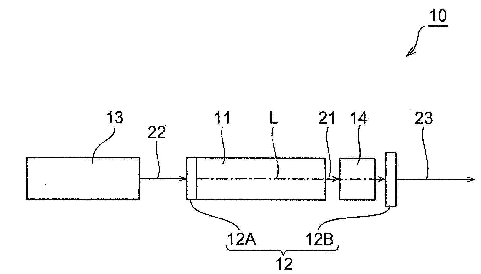
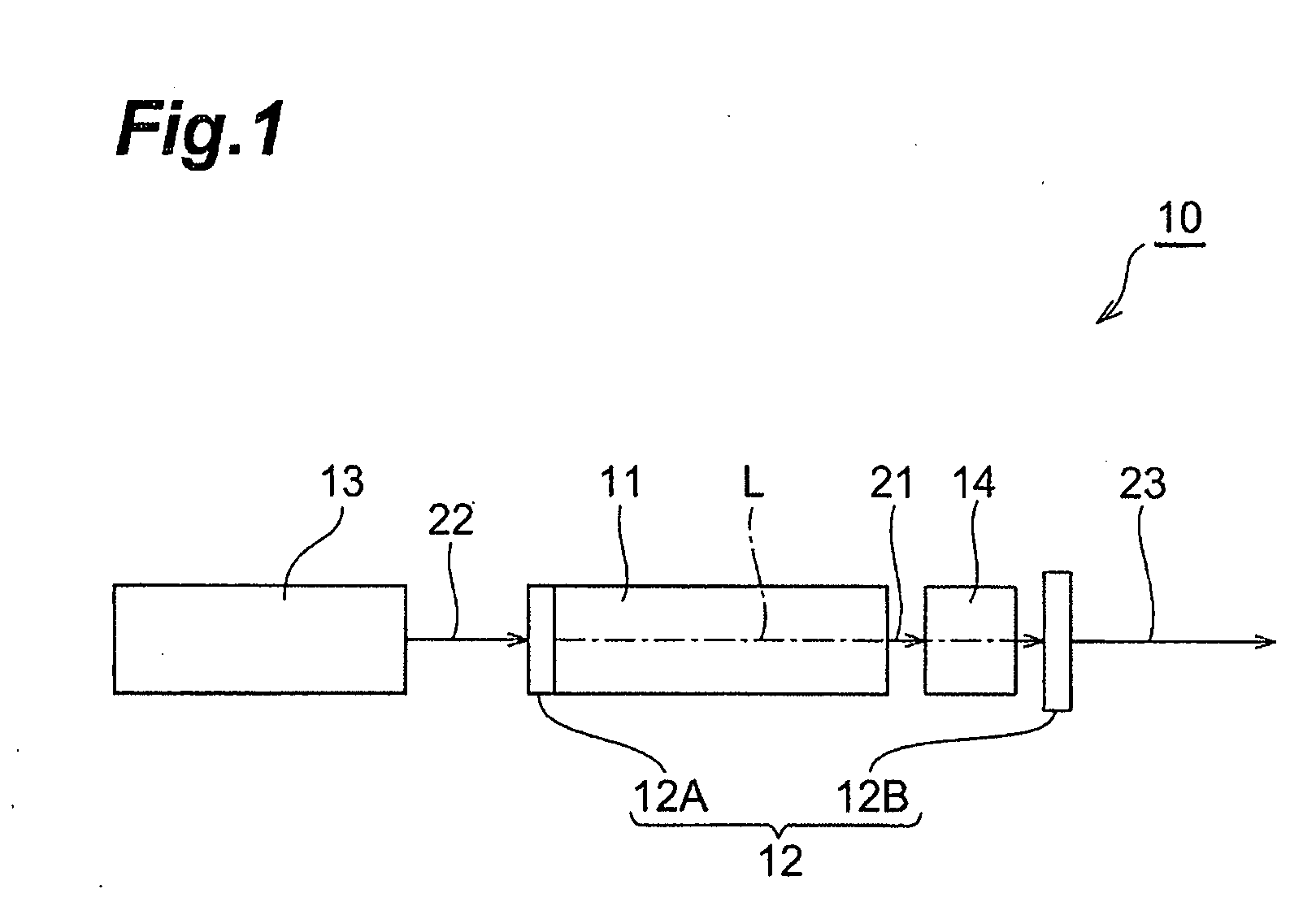
[0048]As shown in FIG. 1, the passively Q-switched laser apparatus (hereinafter referred to simply as “laser apparatus”) 10 has Nd:YAG crystal 11 as a laser medium. The Nd3+:YAG crystal 11 can be excited by light having a wavelength of around 808 nm and emit light having a wavelength of about 1064 nm due to a transition from an upper level to a lower level. The wavelengths each may include an error of ±10 nm for their specific wavelengths. It is noted that in the following descriptions, light emitted from the Nd3+:YAG crystal 11 will be referred to as emitted light 21.

[0049]The Nd3+:YAG crystal 11 is arranged in an optical resonator 12 and the optical resonator 12 is composed of a pair of mirrors (reflecting means) 12A and 12B facing each other. Then, the mirror 12A is transparent to light having a waveleng...


PUM


Abstract

A laser apparatus 10 includes: a laser medium 11 arranged between a pair of reflecting means 12A and 12B of an optical resonator 12 and adapted to be excited to emit light; a saturable absorber 14 arranged on the optical axis L of the optical resonator 12 between the pair of reflecting means, the transmissivity thereof being adapted to increase with the absorption of emitted light 21 from the laser medium; and an excitation light source unit 13 adapted to output light 22 having a wavelength that excites the laser medium. The saturable absorber 14 is a crystalline body having first to third mutually perpendicular crystallographic axes and is arranged in the optical resonator 12 in such a manner as to have different transmissivities for emitted light in two mutually perpendicular polarization directions. In this case, a laser oscillation occurs for emitted light in the polarization direction that shows the greater transmissivity, and it is therefore possible to obtain laser beams having a stabilized polarization direction.

Description

TECHNICAL FIELD[0001]The present invention relates to a passively Q-switched laser apparatus.BACKGROUND ART[0002]Passively Q-switched laser apparatuses (hereinafter referred to simply as “laser apparatuses”) are for generating pulse light and utilized in spectroscopic measurements, geometrical measurements, and nonlinear crystal excitations, etc. In such laser apparatuses, a saturable absorber is arranged together with a laser medium between a pair of mirrors (reflecting means) that constitute an optical resonator. In this arrangement, when light emitted from the laser medium being excited enters the saturable absorber, the emitted light is absorbed by the saturable absorber. The electron density in the excited level of the saturable absorber increases gradually with the absorption of the emitted light, and when the excited level is filled up, i.e., the electron density in the excited level is saturated at some point in time, the saturable absorber becomes transparent. At this time,...

Claims


Application Information

Patent Timeline
Patent Type & Authority Applications(United States)
IPC IPC(8): H01S3/113
CPCH01S3/0014H01S3/0621H01S3/113H01S3/08036H01S3/10061H01S3/0627
Inventor SAKAI, HIROSHIKAN, HIROFUMITAIRA, TAKUNORI
Owner INTER UNIV RES INST NAT INST OF NATURAL SCI
Why Eureka
Try Eureka