Tool-less Rotary Vacuum Wicketter Assembly

Active Publication Date: 2009-01-15
PEARL TECH
View PDF16 Cites 2 Cited by
  • Summary
  • Abstract
  • Description
  • Claims
  • Application Information

AI Technical Summary

Benefits of technology

[0008]Accordingly, it is an object of this invention to provide an improved vacuum wicketter which avoids

Problems solved by technology

These are usually welded or cemented in place, but in some cases are secured by threaded screws, and are not meant to be easily removed.
It is well understood that the manufacture and handling of the plastic film web and products constructed from the film create a significant volume of plastic

Method used


Image

  • Tool-less Rotary Vacuum Wicketter Assembly
  • Tool-less Rotary Vacuum Wicketter Assembly
  • Tool-less Rotary Vacuum Wicketter Assembly

Examples


Embodiment Construction

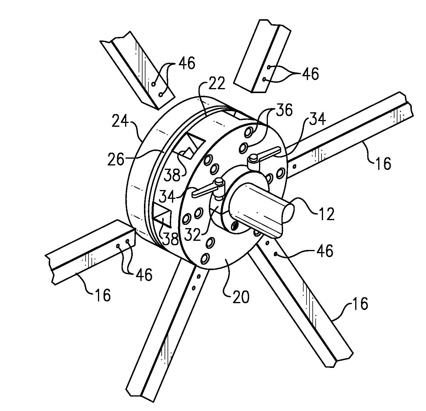
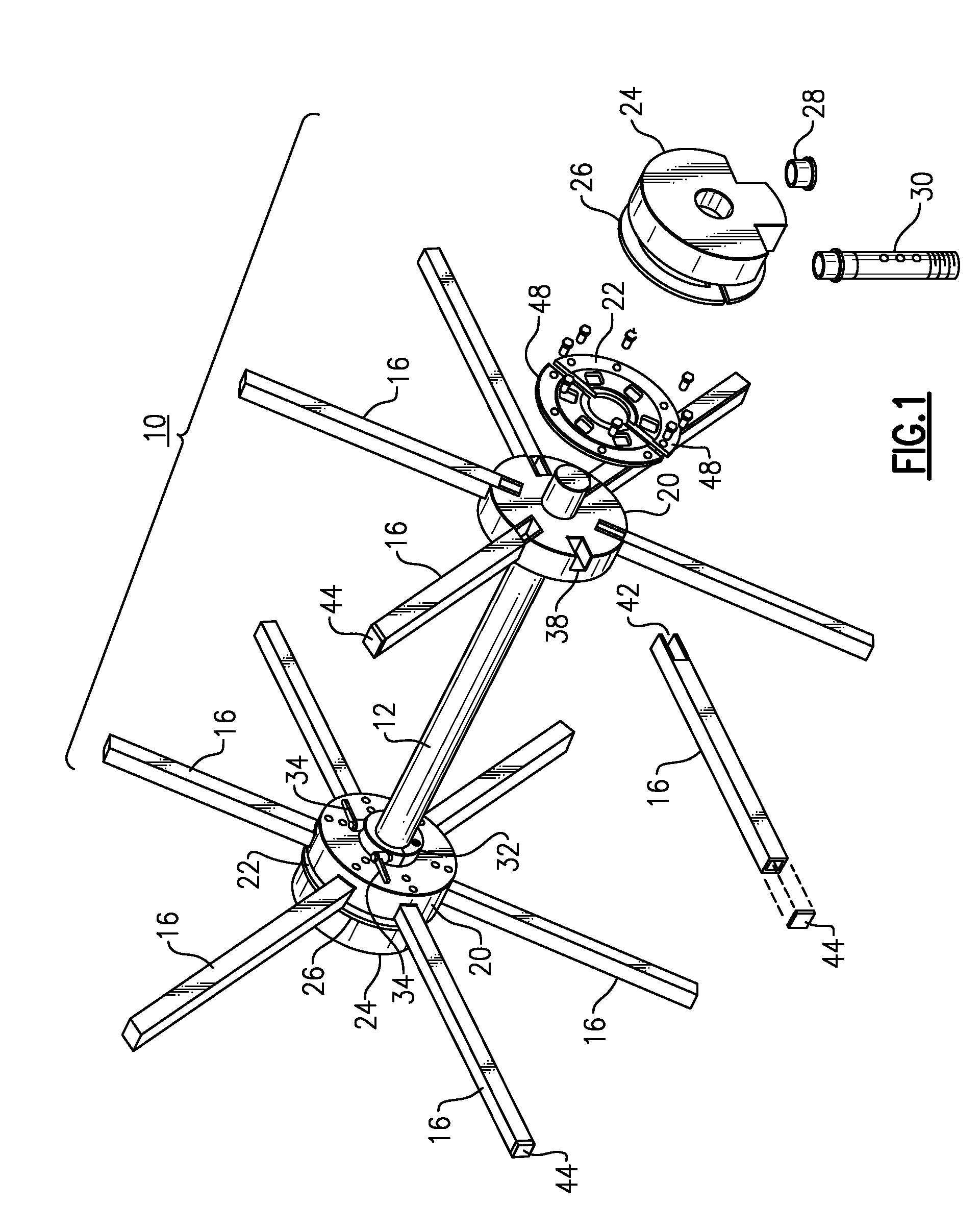
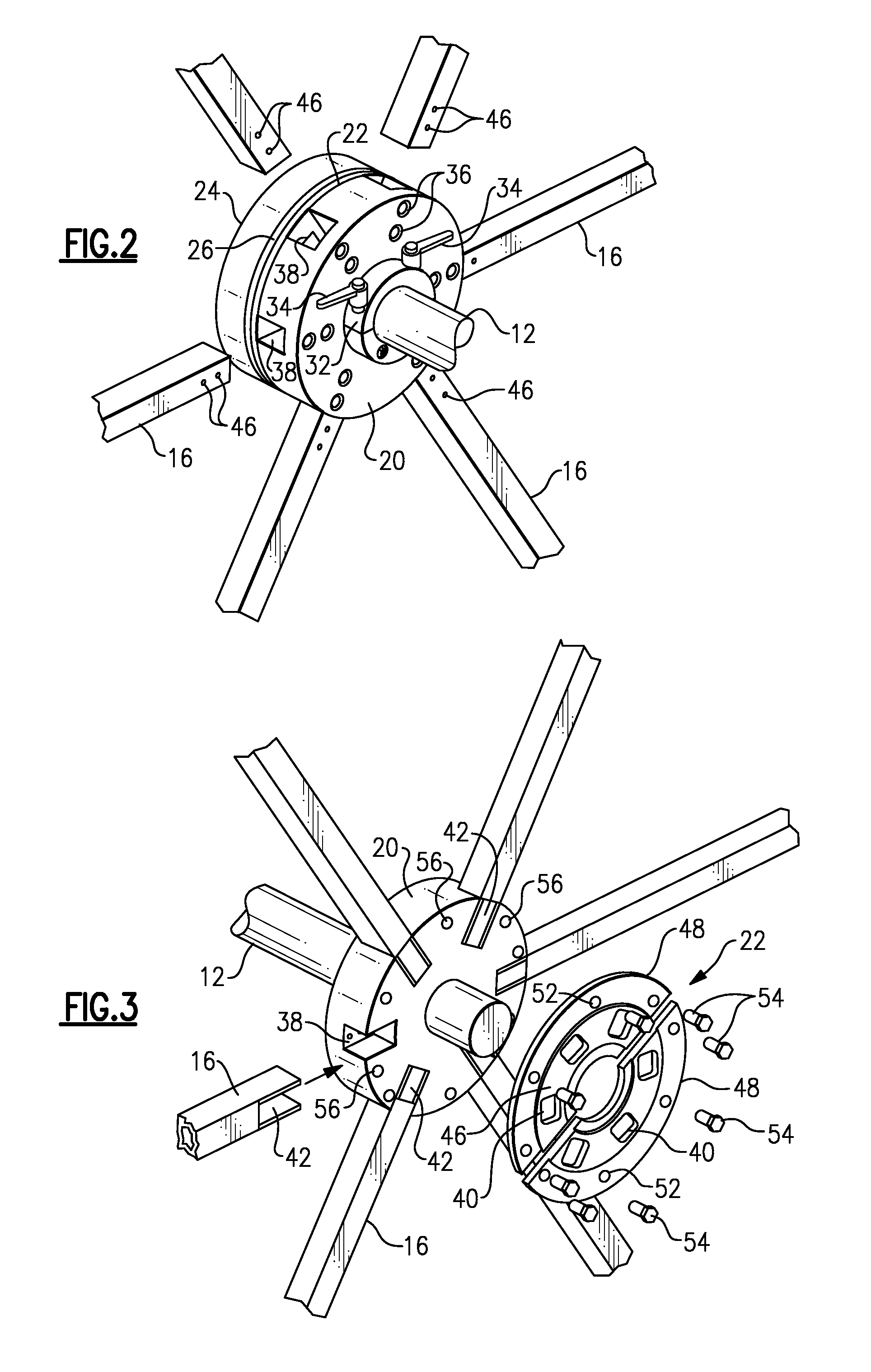
[0029]With reference to the Drawing, FIG. 1 illustrates a rotary transfer arrangement that may be employed in carrying plastic film articles, e.g., bags, from one station to another, for example, from a bag machine to a bag stacking station, such as a wicket plate. Here, the rotary transfer station is in the form of a vacuum wicketter 10, in which there is a rotary shaft 12 that carries a pair of hub assemblies 14, 14, spaced a pre-set distance from one another, and each of which carries an array of vacuum pickup arms 16. These arms project radially from the hub assemblies and are angularly spaced about the axis of the hub assemblies. In this example, for each hub assembly there are six arms 16, at sixty-degree spacing. However, rotary wicketters may have eight arm arrays, in which the arms are spaced at forty-five degree intervals. Other wicketters have other configurations, e.g., nine arms at forty-degree intervals.

[0030]As shown with further reference to FIGS. 2 and 3, the hub as...


PUM


Abstract

A rotary vacuum wicketting arrangement has a rotary hub body positioned on a shaft or spindle and supporting a number of pickup arms, and a non-rotating vacuum spinning head that provides vacuum to the rotating hub body and pickup arms over a portion of their arcuate travel. The rotary hub body is provided with a lock ring formed or a pair of half rings with hand levers so that the position of the hub body on the shaft can be adjusted toollessly. The pickup arms are held in place in their sockets by ball and spring detents, so that they can be pulled out for cleaning and reinserted without tools. A friction fitted plug closes off the end of each arm.

Description

BACKGROUND OF THE INVENTION[0001]This invention relates to plastic film handling equipment and is more specifically directed to a machine for transporting a workpiece formed from a web of plastic film material. An example of such a workpiece is a plastic bag, which is produced at a bag machine or similar station and is to be transported to a collection station. The invention is concerned with a rotary wicketter, i.e., a rotary transport device in which an array of vacuum arms, i.e., hollow perforated bars, extend radially out from a rotor hub, and in which vacuum is applied for a portion of the rotation to carry the plastic film workpiece from one station to another.[0002]Vacuum wicketters are widely used in the plastic film trade, and their general construction and operation is well known. The general design and operation of a wicketter can be understood, e.g., from Gaffal U.S. Pat. No. 6,702,277 (Mar. 9, 2004), Stock U.S. Pat. No. 5,074,735 (Dec. 24, 1991), and Sample et al. U.S. ...

Claims


Application Information

Patent Timeline
IPC IPC(8): B65H39/00
CPCB31B19/98B31B2219/927B65H29/40B65H2402/5156B65H2701/191B65H2404/6551B65H2406/3612B65H2601/324B65H2402/64B31B70/984B65H2402/51B65H2402/60
Inventor TEWKSBURY, ROBERT J.CLARK, MARK J.
Owner PEARL TECH
Why Eureka
Try Eureka