Automatic transmission including clutch devices

a clutch device and automatic transmission technology, applied in the direction of fluid couplings, gearings, couplings, etc., can solve the problems of high cost of automatic transmission manufacture and the fact that the automatic transmission is not designed for economical manufacture, so as to reduce the cost of automatic transmission manufacture and reduce the cost of production. , the effect of large torqu

Inactive Publication Date: 2009-01-22
TOYOTA JIDOSHA KK
View PDF4 Cites 9 Cited by
  • Summary
  • Abstract
  • Description
  • Claims
  • Application Information

AI Technical Summary

Benefits of technology

[0006]In the automatic transmission constructed according to the principle of this invention, the relative rotation of the first and second drums is inhibited by the fitting portion, so that the first and second drums are rotated together. Thus, the first and second drums are fixed together, by simply fitting the first drum in the second drum, without requiring a welding process, so that the automatic transmission can be manufactured at a relatively low cost, in a relatively small number of process steps.
[0007]In a preferred form of this invention, the first drum includes a first inner cylindrical wall and a first outer cylindrical wall that are coaxial with each other, and a first bottom wall connecting corresponding axial end portions of first and second cylindrical walls, while the second drum includes a second inner cylindrical wall and a second outer cylindrical wall that are coaxial with each other, and a second bottom wall connecting corresponding axial end portions of the second inner and outer cylindrical walls. In this form of the invention, the fitting portion is a spline-fitting portion constituted by first spline teeth formed on an inner circumferential surface of the first inner cylindrical wall, and second spline teeth which are formed on an outer circumferential surface of the second cylindrical wall. The mutually meshing first and second spline teeth assure even or uniform distribution of a torque acting on the first and second drums, unlike a key and a key slot meshing with the key. Accordingly, the spline-fitting portion can withstand a comparatively large torque.
[0008]In a first advantageous arrangement of the above-described preferred form of the present invention, the second drum further includes a second annular protrusion extending from a radially intermediate part of the second bottom wall in an axial direction thereof toward the first bottom wall, for abutting contact with the first bottom wall, and the abutting portion consists of the second annular protrusion. This arrangement inhibits the relative axial movement of the first and second drums, without requiring a complicated mechanism, and is effective to reduce the required number of components of the automatic transmission and accordingly reduce the cost of manufacture of the automatic transmission.
[0009]In the automatic transmission according to the above-described advantageous arrangement, the second piston preferably includes a base portion slidably received in a second annular recess formed between the second annular protrusion and the second outer cylindrical wall, a sleeve portion extending from a radially outer end of the base portion remote from the base portion, through an annular space formed between the first outer cylindrical wall and the second outer cylindrical wall, and a presser portion extending from an axial end of the sleeve portion beyond a corresponding axial end of the first outer cylindrical wall in an axial direction of the sleeve portion toward the second clutch. This arrangement permits a reduced distance of axial spacing between the first and second clutches, and a reduced distance of radial spacing between these two clutches, so that the automatic transmission can be made compact in the axial and radial directions.

Problems solved by technology

However, a process of welding together the plurality of drums requires a large number of process steps, which require a high cost of manufacture of the automatic transmission.
Thus, the known automatic transmission is not designed for economical manufacture.

Method used


Image

  • Automatic transmission including clutch devices
  • Automatic transmission including clutch devices
  • Automatic transmission including clutch devices

Examples


Embodiment Construction

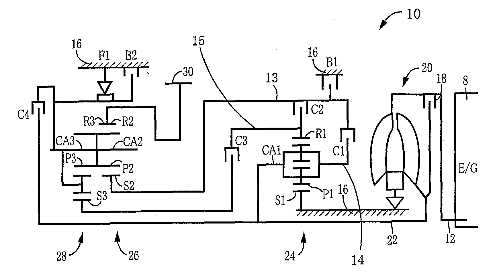
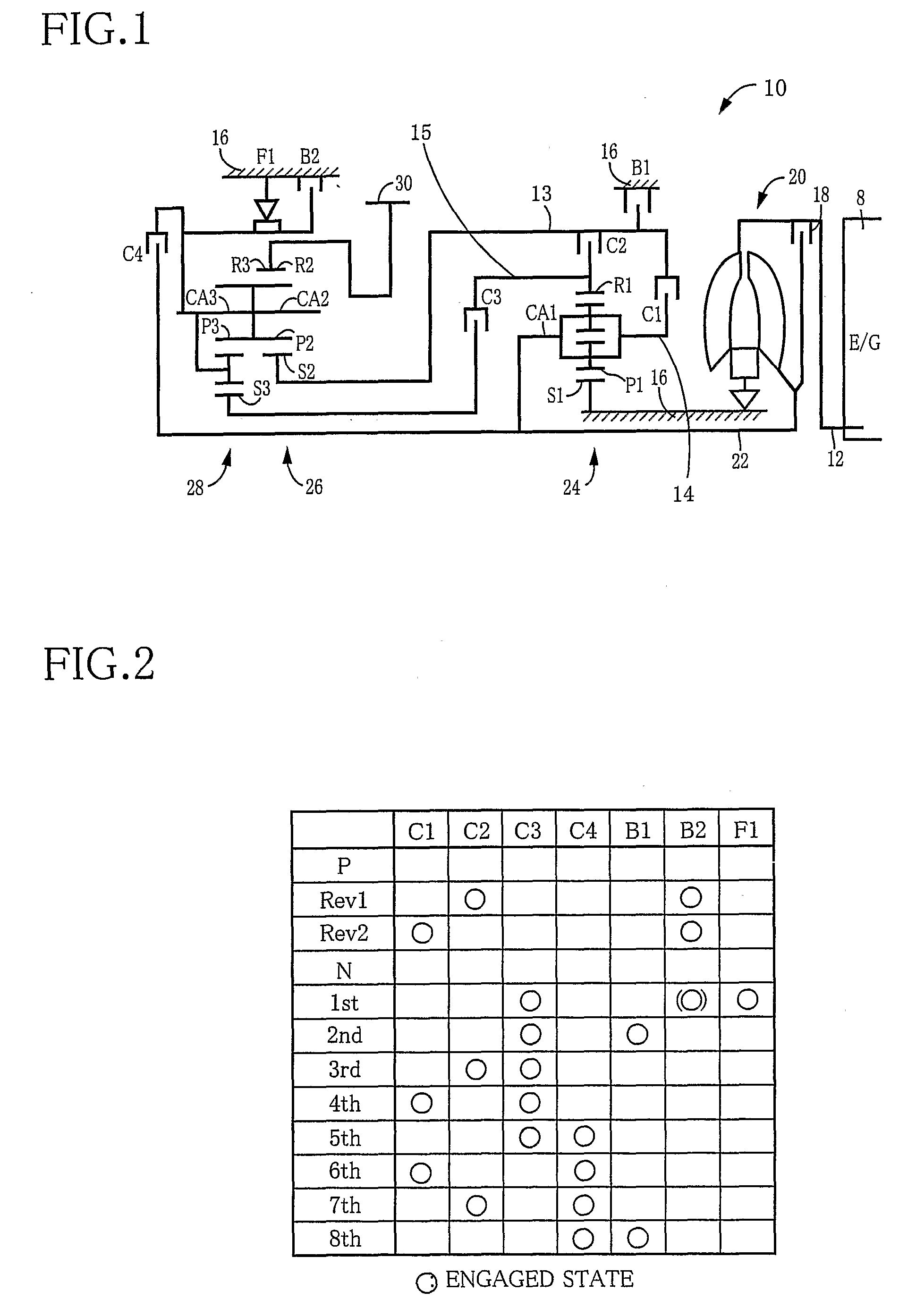
[0015]Referring first to the schematic view of FIG. 1, there is shown an automatic transmission 10 of a vehicle constructed according to one embodiment of this invention. The automatic transmission 10 is disposed between an engine 8, and drive wheels (not shown) of the vehicle, and is constructed to transmit an output of the engine 8 to the drive wheels. The vehicle has a body to which a stationary member in the form of housing 16 is fixed. Within this housing 16, there are accommodated a torque converter 20, an input shaft 22 connected to the torque converter 20, a first planetary gear set 24, a second planetary gear set 26, and a third planetary gear set 28, such that these major components 20, 22, 24, 26, 28 are arranged in the order of description in the left direction as seen in FIG. 1. The torque converter 20 is provided with a lock-up clutch 18 arranged to transmit a rotary motion of a crankshaft 12 of the engine 8 through a power transmitting medium in the form of a fluid. T...


PUM


Abstract

An automatic transmission including a first clutch selectively connecting a first rotary member and a second rotary member disposed coaxially with the first rotary member, a second clutch selectively connecting the first rotary member and a third rotary member disposed coaxially with the first rotary member, a first drum in which a first piston of the first clutch is axially slidably received, a second drum disposed coaxially with the first drum, to accommodate the first drum, and in which a second piston of the second clutch is axially slidably received, an abutting portion abutting contact of the first and second drums with each other in an axial direction of the first and second drums, and a fitting portion at which the first drum is fitted in the second drum and that inhibits relative rotation of the first and second drums about a common axis of the first and second drums.

Description

TECHNICAL FIELD[0001]The present invention relates in general to an automatic transmission including clutch devices, and more particularly to an automatic transmission which includes clutch devices and which is economical to manufacture.BACKGROUND ART[0002]There is known an automatic transmission of a type incorporating a plurality of frictional coupling devices which are disposed at respective different radial positions so as to reduce the required axial dimension of the automatic transmission. JP-7-198037 A discloses an example of such type of automatic transmission in which the frictional coupling devices are disposed at the respective radial positions so as to improve the efficiency of lubrication of the frictional coupling devices.[0003]In the automatic transmission disclosed in the above-identification publication, a plurality of drums in which pistons of the respective frictional coupling devices are axially slidably received are fixed to each other by welding. However, a pro...

Claims


Application Information

Patent Timeline
Patent Type & Authority Applications(United States)
IPC IPC(8): F16D25/10F16D25/0638F16H3/62F16H3/66F16H57/02F16H57/023
CPCF16D25/0638F16D25/10F16H3/663F16H57/08F16H2057/087F16H2200/006F16H2200/2007F16H2200/2097F16H63/3026F16H63/30F16H3/66
Inventor KATO, NAOKIMIYAZAKI, TERUFUMI
Owner TOYOTA JIDOSHA KK
Why Eureka
Try Eureka