
Wing leading edge having vortex generators

Active Publication Date: 2009-01-22
TEXTRON INNOVATIONS
View PDF19 Cites 33 Cited by
  • Summary
  • Abstract
  • Description
  • Claims
  • Application Information

AI Technical Summary

Benefits of technology

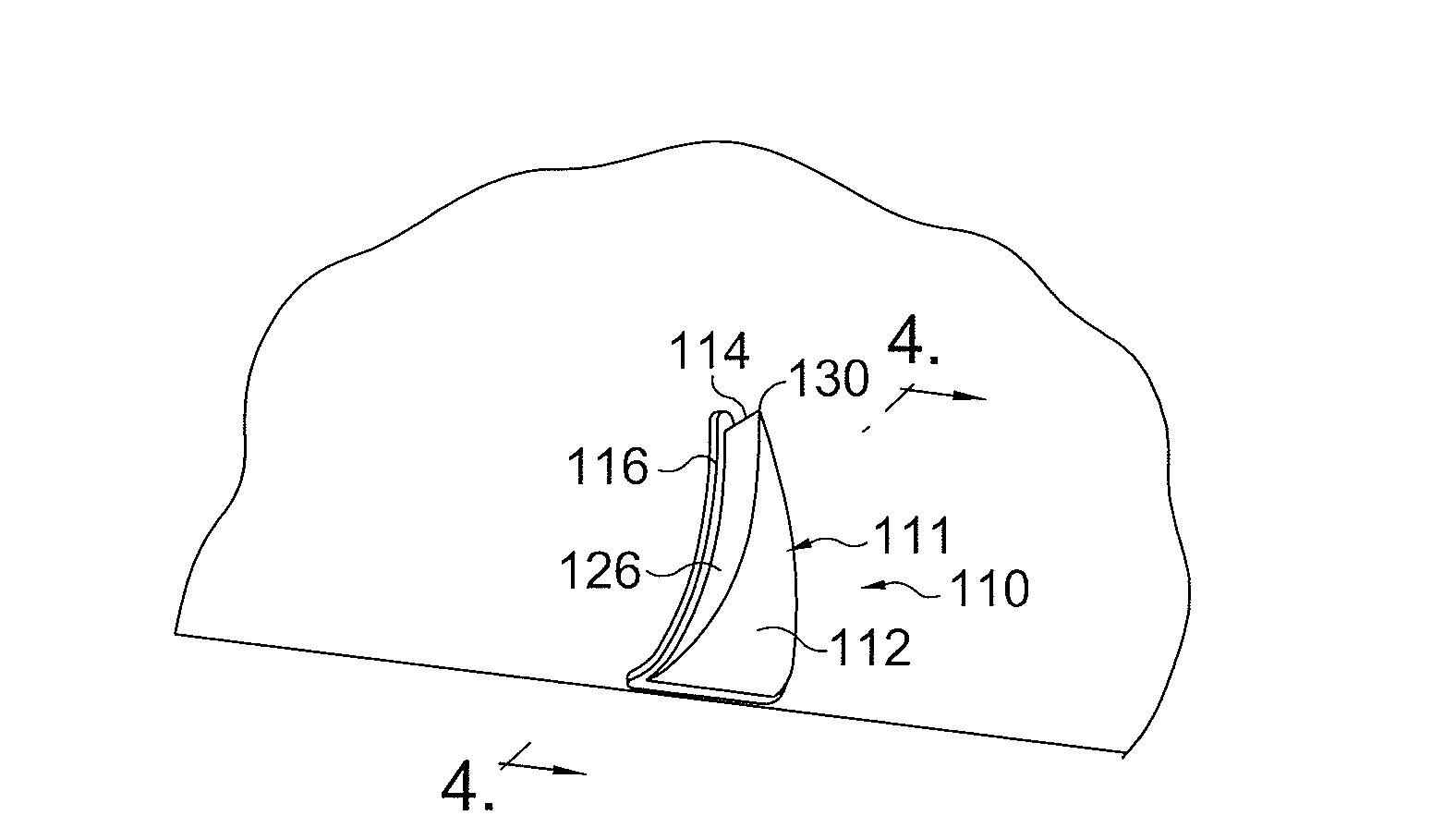
[0009]The protrusion is adapted such that it minimizes flow separation from the wing, especially when the aircraft approaches stall conditions. Structurally speaking, this flow separation minimization, in one embodiment, is achieved by configuring the protrusions such that each has a ramped upper face and two laterally converging sides. In some embodiments the protrusions are vortex generators.
[0013]A method is also disclosed. Embodiments of the method include improving the aerodynamics of an aircraft wing by (i) providing a flexible inflatable member; (ii) installing the flexible inflatable member along the leading edge of an aircraft for the purpose of preventing ice buildup by inflating and deflating it; and attaching one or more aerodynamic devices to the inflatable member for the purpose of generating vortices.
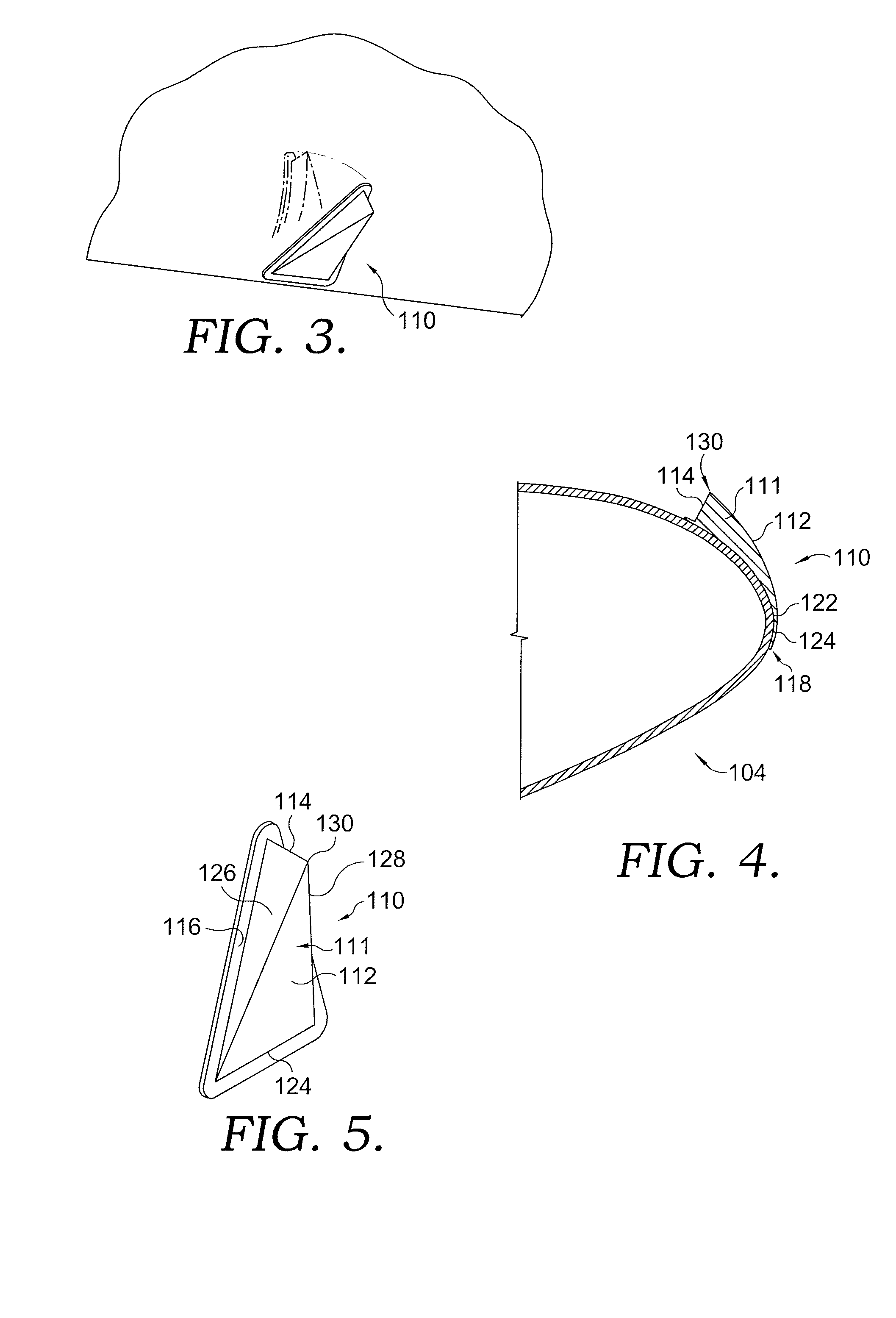
[0014]In embodiments, the method includes constructing the aerodynamic devices of a flexible material such that said devices are able to flex along with said inflatable member which is also, in embodiments, constructed of a flexible material. For example, both could be constructed of a neoprene material in embodiments. In a further embodiment, the devices are adapted such that they minimize flow separation when the aircraft approaches a stall.

Problems solved by technology

The accumulation of ice and other contaminants on aircraft wings has been an ongoing problem.
Thus, the cycled expansions mitigate the ice problem, but do not eliminate it completely.
One problem created by residual ice occurs at or near a stall.
This flow separation dramatically decreases lift (sometimes suddenly), increases drag, and immediately shifts the aircraft's pressure center forward.
Depending on the aircraft's design, a stall can expose extremely adverse properties of balance and control—even in ideal conditions.
But these issues are exacerbated when the aerodynamically ideal wing surfaces become contaminated with some foreign substance, such as ice or frost.
Ice, frost, or other contaminating surface roughness can increase the speed at which the stall occurs.
Thus, conventionally, ice buildup has been shown to interfere with control, especially as the speed and attack angle are near or at stall conditions.

Method used


Image

  • Wing leading edge having vortex generators
  • Wing leading edge having vortex generators
  • Wing leading edge having vortex generators

Examples


Embodiment Construction

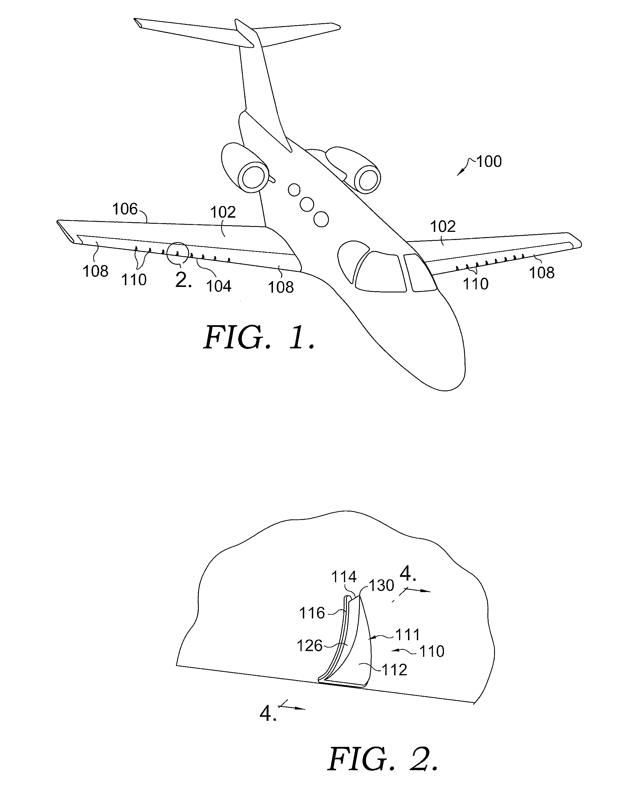
[0021]An embodiment for an aircraft 100 is shown in FIGS. 1-5. As can be seen from the figure, aircraft 100 includes first and second wings 102. One will understand that the configuration of each is the flip-side equivalent of the other. Each wing has a leading edge 104 and a trailing edge 106. With respect to each, the leading edge 104 includes an deice boot 108.

[0022]One skilled in the art will recognize that devices like boot 108 typically are constructed of a flexible material which is capable of being elastically expanded out, and then contracted back while maintaining structural integrity. In one embodiment, this boot is constructed of neoprene rubber, which is a well-known synthetic material which is abrasion-resistant, chemical-resistant, waterproof, and elastic. It is, of course, possible that boot 108 could be constructed of other materials.

[0023]Functionally speaking, boot 108 is expanded using a plurality of spanwise extending inflatable tubes which are stitched into the...


PUM


Abstract

An arrangement of devices as well as a method for improving the aerodynamics of an aircraft wing are disclosed. In embodiments, a plurality of vortex generators are attached in span-wise alignment on an deice boot along the wing's leading edge. The vortex generators are, in embodiments, constructed of a flexible material such that they are able to be expanded along with the boot during inflation and deflation thus mechanically involving the aerodynamic devices in the ice-shedding process.

Description

BACKGROUND OF THE INVENTION[0001]1. Field of the Invention[0002]The invention relates generally to aerodynamics. More specifically, the invention relates to the field of aircraft wing design.[0003]2. Description of the Related Art[0004]The accumulation of ice and other contaminants on aircraft wings has been an ongoing problem. With respect to ice buildup, artisans have taken a number of approaches to dealing with the problem. Some solutions have involved the administration of heat to the leading edge or other locations on the wing. Other techniques involve the use of chemicals to induce shedding. Additional solutions have involved the use of mechanical arrangements.[0005]One mechanical arrangement involves the use of what is referred to as a “dedeice boot.” Dedeice boots include flexible sheets of rubber which are adhered to the leading edge of the wing and have span-wise inflatable tubes which are stitched into the rubber matting. When the tubes are inflated, the boot causes the a...

Claims


Application Information

Patent Timeline
IPC IPC(8): B64C23/00
CPCY02T50/162B64C23/06Y02T50/10
Inventor RINCKER, GREGORY A.CLEVELAND, KENTON A.HAMMER, JAMES L.
Owner TEXTRON INNOVATIONS
Learn More