
LED chip package structure with high-efficiency light-emitting effect and method of packaging the same

a technology of led chip and package structure, which is applied in the direction of identification means, lighting and heating apparatus, instruments, etc., can solve the problems of time-consuming known first packaging process, known led package structure that does not offer a good display for users, etc., and achieves the effect of simple process and less time for manufacturing process

Inactive Publication Date: 2009-01-22
HARVATEK CORPORATION
View PDF2 Cites 19 Cited by
  • Summary
  • Abstract
  • Description
  • Claims
  • Application Information

AI Technical Summary

Benefits of technology

The present invention provides an LED chip package structure and a method of packaging LED chips with high-efficiency light-emitting effect. The LED chip package structure includes a substrate unit, a light-emitting unit, and a package colloid unit. The LED chips are arranged on the substrate body via an adhesive or a hot pressing method. The package colloids are respectively covered on the LED chips, and a frame unit is optionally added to expose the top surface of each package colloid. The LED chip package structure has a continuous series of light-generating areas, which prevents dark bands between LED chips. The method of packaging LED chips is simple and reduces manufacturing time. The LED chip package structure can be used for any type of light source such as a back light module, a decorative lamp, a lighting lamp, or a scanner.

Problems solved by technology

Hence, the known first packaging process is time-consuming.
Moreover, because the fluorescent colloids 4a are separated from each other, a dark band is easily produced between the two fluorescent colloids 4a and the two LEDs 2a. Hence, the known LED package structure does not offer a good display for users.
Hence, the known first LED package structure does not offer a good display for users.
However, the triggered area of the stripped package colloid is not uniform, so the light-emitting efficiency of the light bar is not good.

Method used


Image

  • LED chip package structure with high-efficiency light-emitting effect and method of packaging the same
  • LED chip package structure with high-efficiency light-emitting effect and method of packaging the same
  • LED chip package structure with high-efficiency light-emitting effect and method of packaging the same

Examples


first embodiment

[0034]Referring to FIGS. 3, 3a to 3d, and 3A to 3D, the present invention provides a method of packaging LED chips package structure with high-efficiency light-emitting effect. The method comprises: referring to FIGS. 3a and 3A, providing a substrate unit 1, the substrate unit having a substrate body 10, and a positive electrode trace 11 and a negative electrode trace 12 respectively formed on the substrate body 10 (S100). The substrate unit 1 can be a PCB (Printed Circuit Board), a flexible substrate, an aluminum substrate, a ceramic substrate, or a copper substrate. In addition, both the positive electrode trace 11 and the negative electrode trace 12 can be aluminum circuits or silver circuits. The layouts of the positive electrode trace 11 and the negative electrode trace 12 are determined by different needs.

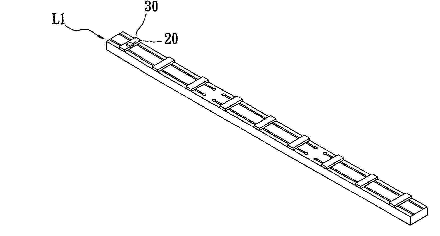
[0035]Referring to FIGS. 3b and 3B, the method of the first embodiment further comprises: arranging a plurality of LED chips 20 on the substrate body 10 via a matrix method t...

second embodiment

[0043]After the step of S204, referring to FIGS. 5a and 5A, the method of the second embodiment further comprises: transversely cutting the stripped package colloids 3 along a line between each two adjacent and longitudinal LED chips 20 to form a plurality of package colloids 30′ that are separated from each other and respectively covered on the corresponding LED chips 20 (S206).

[0044]Referring to FIGS. 5b and 5B, the method of the second embodiment further comprises: respectively covering and filling a frame unit 4 on the substrate body 10 between each two adjacent package colloids 30′ via a second mold unit M2 (S208). Moreover, the second mold unit M2 is composed of a second upper mold M21 and a second lower mold M22 for supporting the substrate body 10. The second upper mold M21 has a second channel M210 corresponding to the frame unit 4. The second channel M210 has a height the same as that of each package colloid 30′ and the second channel M210 has a width the same as that of t...

third embodiment

[0047]After the step of S306, referring to FIGS. 6a and 6A, the method of the third embodiment further comprises: respectively covering and filling a plurality of stripped frame layers 4′ on the substrate body 10 between each two longitudinal and adjacent package colloids 30′ via a third mold unit M3 (S308).

[0048]The third mold unit M3 is composed of a third upper mold M31 and a third lower mold M32 for supporting the substrate body 10. The third upper mold M31 has a plurality of third channels M310 corresponding to the longitudinal LED chip rows 2. Each third channel M310 has a height the same as that of each corresponding package colloid 30′ and each third channel M310 has a width larger than that of each corresponding package colloid 30′.

[0049]Finally, referring to FIGS. 6a, 6b, and 6B, the method of the third embodiment further comprises: transversely cutting the stripped frame layers 4′ and the substrate body 10 along a line between each two adjacent and longitudinal LED chips ...


PUM

PropertyMeasurementUnit
flexibleaaaaaaaaaa
heightaaaaaaaaaa
widthaaaaaaaaaa

Abstract

An LED chip package structure with high-efficiency light-emitting effect includes a substrate unit, a light-emitting unit, and a package colloid unit. The substrate unit has a substrate body, and a positive electrode trace and a negative electrode trace respectively formed on the substrate body. The light-emitting unit has a plurality of LED chips arranged on the substrate body, and each LED chip has a positive electrode side and a negative electrode side respectively and electrically connected with the positive electrode trace and the negative electrode trace of the substrate unit. The package colloid unit has a plurality of package colloids respectively covered on the LED chips.

Description

BACKGROUND OF THE INVENTION[0001]1. Field of the Invention[0002]The present invention relates to an LED chip package structure and a method of packaging the same, and particularly relates to a light socket structure for an LED chip package structure which emits light highly efficiently and a method of packaging the same.[0003]2. Description of the Related Art[0004]Referring to FIG. 1, a known first method for packaging LED chips is shown. The known first method includes: providing a plurality of packaged LEDs that have been packaged (S800); providing a stripped substrate body that has a positive electrode trace and a negative electrode trace (S802); and then, arranging each packaged LED on the stripped substrate body in sequence and electrically connecting a positive electrode side and a negative electrode side of each packaged LED with the positive electrode trace and the negative electrode trace of the substrate body (S804).[0005]Referring to FIG. 2, a known second method for pack...

Claims


Application Information

Patent Timeline
Patent Type & Authority Applications(United States)
IPC IPC(8): H01L33/00H01L21/00H01L33/52
CPCB29C33/0022F21Y2103/003F21K9/00G09F9/33G09F13/22H01L24/97H01L33/52H01L2224/16225H01L2224/48091H01L2224/97H01L2924/01013H01L2924/01029H01L2924/01047H01L2924/01082B29C45/14655F21K9/30H01L2924/12041H01L2924/01074H01L2924/01005H01L2224/81H01L2924/00014H01L2224/85F21K9/20F21Y2103/10F21Y2115/10H01L2924/15747H01L2924/15787H01L2924/00
Inventor WANG, BILYCHUANG, JONNIEWU, WEN-KUEI
Owner HARVATEK CORPORATION
Learn More