Spectral discrimination apparatus and method

a spectral discrimination and apparatus technology, applied in the field of spectral discrimination apparatus, can solve the problems of introducing complexity of control and interpretation, confocal aperture would have a deleterious effect on spectral resolution, slow and expensive, etc., and achieves high switching speed and production very cheap and controlled

Inactive Publication Date: 2009-01-22
MEDICAL RESEARCH COUNCIL
View PDF6 Cites 8 Cited by
  • Summary
  • Abstract
  • Description
  • Claims
  • Application Information

AI Technical Summary

Benefits of technology

[0018]The frequency selection means, consisting in the simplest embodiment of a thin perforated disc, or an opaque disc with transparent regions, or a number of such discs, is positioned after the dispersive element and in the aperture plane containing the streak in such a way that the perforations control the admission of light of different wavelengths to the detector. Such discs can be produced very cheaply and controlled by a single cheap rotary motor or a small number of such motors, which can effect a switch of wavelength much more rapidly than the linear actuators of Engelhardt. The rotation of the disc to definite angular positions allows the wavelength of detection to be varied in steps. The disc can also be spun continuously to achieve high speeds of switching or subjected to an angular rotary vibration, so alternating rapidly between positions or scanning through a series of such positions.

Problems solved by technology

Also, enlargement of the confocal aperture would have a deleterious effect on the spectral resolution.
Also, if, as he taught, the slits in the plural masks are variable both in width and position, a large number of independent linear actuators are needed, which are slow and expensive and introduce complexities of control and interpretation.
Finally, the use of plural detectors, though advantageous for the simultaneous detection of light of different wavelengths, militates against the production of a cheap or compact instrument.

Method used


Image

  • Spectral discrimination apparatus and method
  • Spectral discrimination apparatus and method
  • Spectral discrimination apparatus and method

Examples


Embodiment Construction

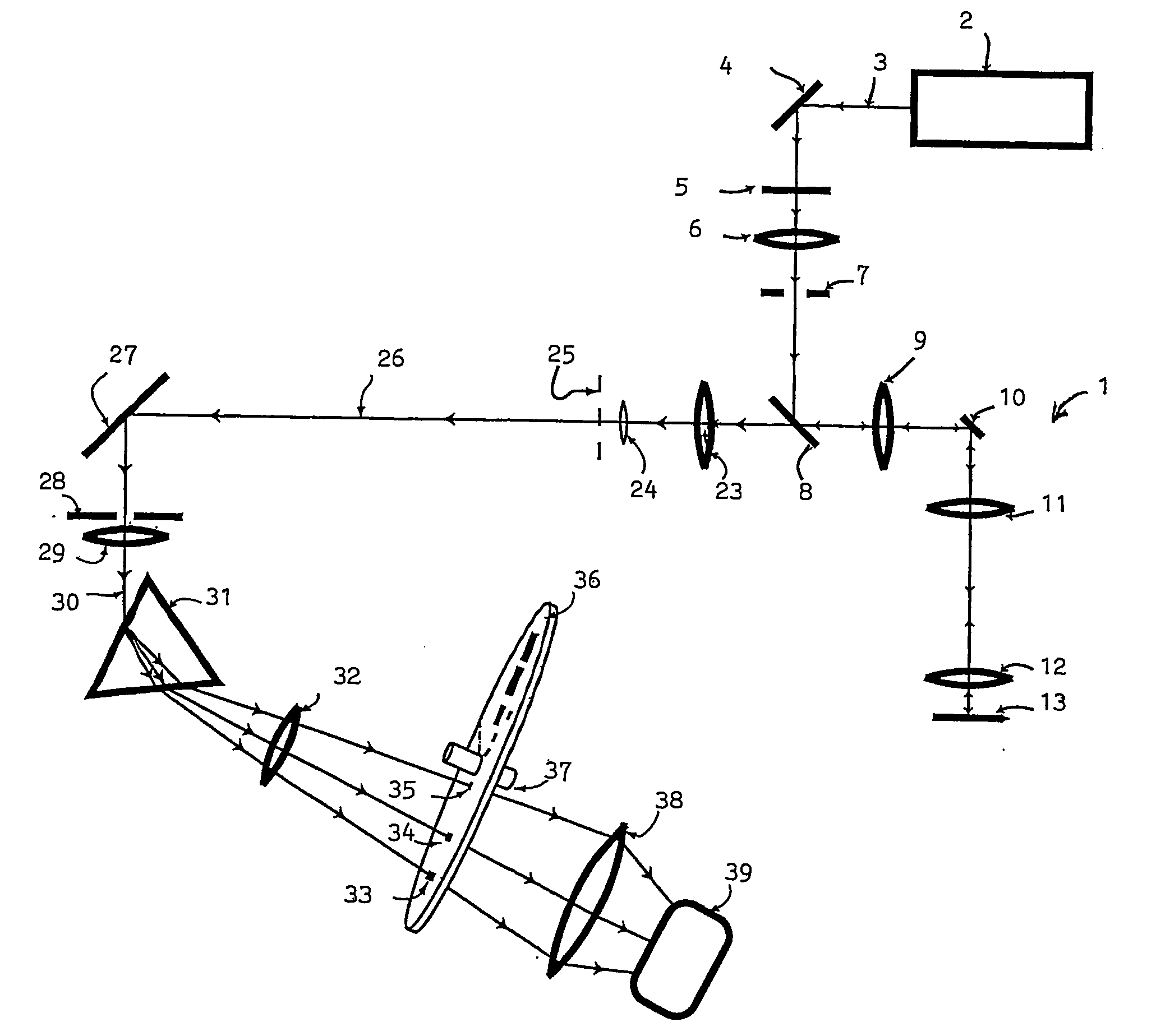
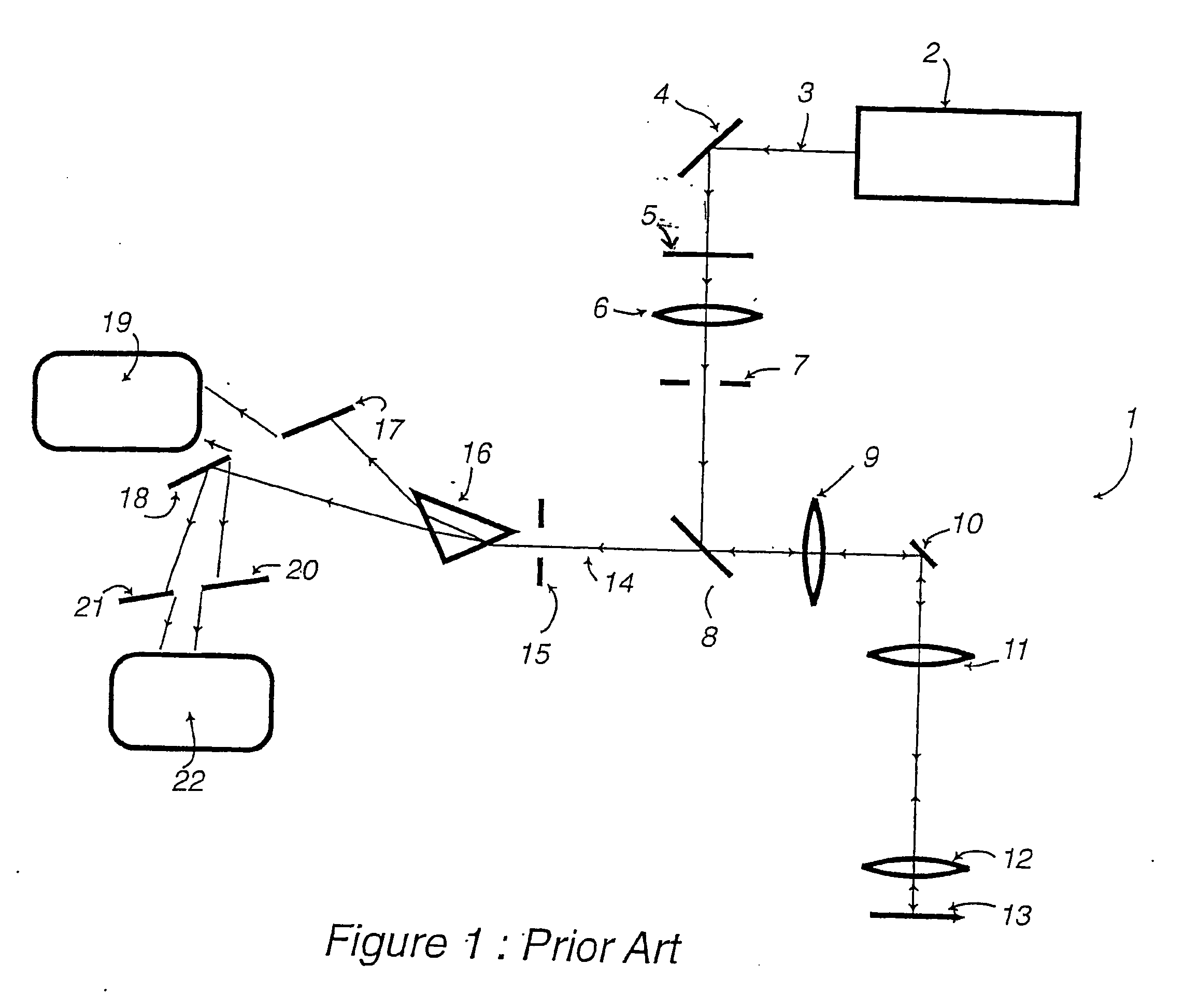
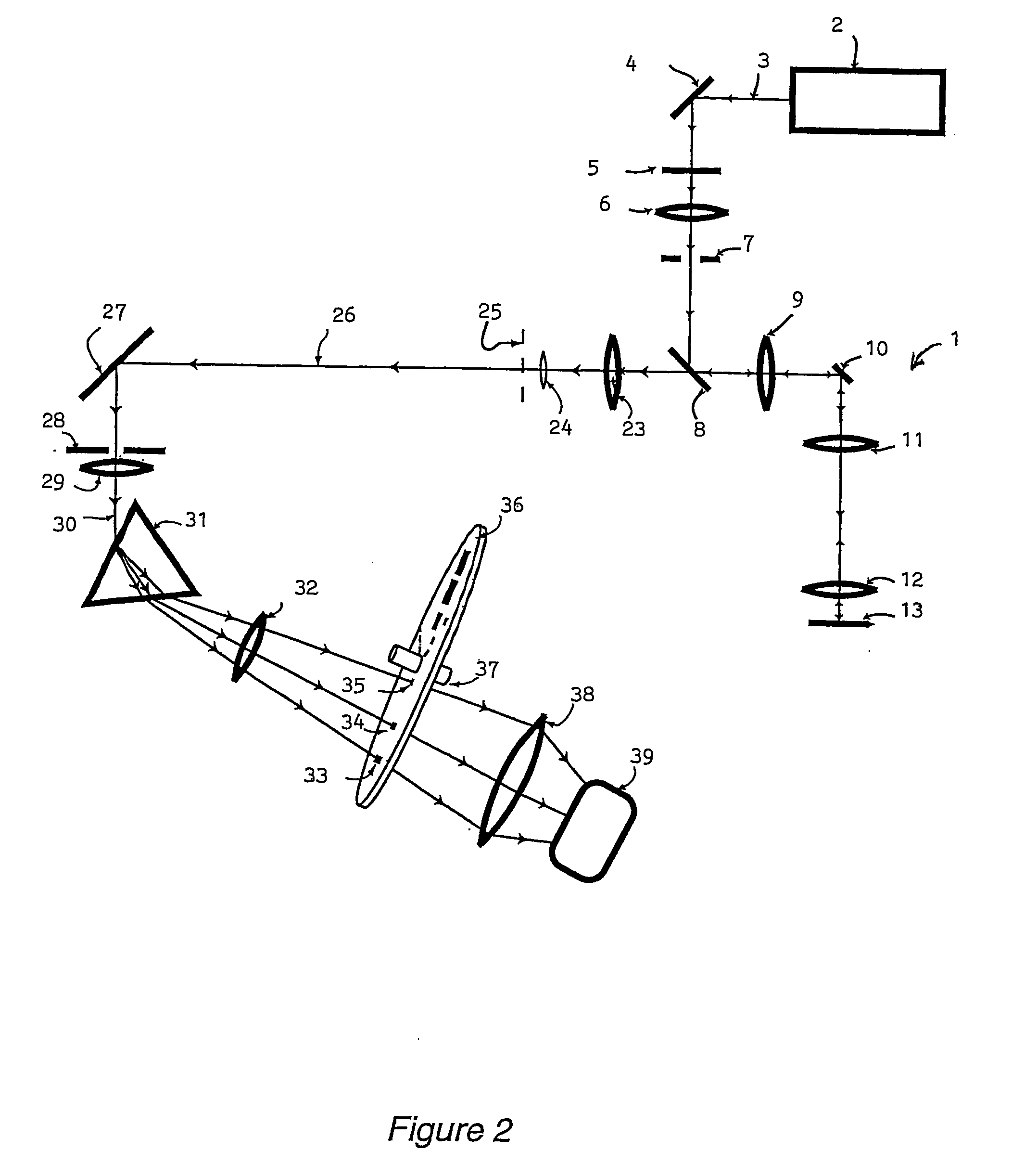
[0024]Referring to FIG. 2, the spectral discrimination apparatus (shown by components referenced 31 to 37) is shown in a confocal microscope 1 having scanning components 2 to 13 corresponding to similarly numbered components in FIG. 1. In FIG. 2, light is shown entering a Keplerian telescope, consisting of lenses 23 and 24. The light entering lens 23 is equivalent to the light beam 14 of FIG. 1: it consists of the light emitted by the specimen 13 in the scanning microscope 1. The telescope produces a focussed image of the back focal plane of the objective lens of the scanning microscope in a plane 25 which is, according to standard optical terminology, an aperture plane. The image of the back focal plane thus formed by the telescope is greatly reduced in size relative to the actual aperture size in the objective lens. Light beam 26 passes from this reduced-size image to a diaphragm 28, being deflected for convenience by a reflector 27. The diaphragm 28 is situated in an image plane ...


PUM

PropertyMeasurementUnit
frequencyaaaaaaaaaa
transmissionaaaaaaaaaa
scanning optical microscopeaaaaaaaaaa

Abstract

There is provided spectral discrimination apparatus for use in a scanning optical microscope, the spectral discrimination apparatus comprising dispersive means (31) and frequency selective means including a rotatable disc (36) or discs. The discs are formed with apertures or spiral slots which, on rotation of the disc or discs, controls the frequency of light transmitted by the apparatus. The apparatus includes a detector (39) for receiving light from the frequency selective means. The, or each, rotatable disc (36) is positioned at an aperture plane after the dispersive means (31), although this is not essential if the rotatable disc has its outer periphery shaped to provide a cam surface engaged by a cam follower. There is also provided a method of spectral discrimination in a scanning optical microscope, comprising dispersing the light and passing the light through frequency selective means in which the form of rotating discs controls the frequency of transmitted light.

Description

FIELD OF THE INVENTION[0001]This invention relates to spectral discrimination apparatus for use in scanning optical microscopes and to a method of use of such apparatus.BACKGROUND TO THE INVENTION[0002]Several types of scanning optical microscope are now used. These include the confocal microscope and the multiphoton-excitation fluorescence microscope. In many such microscopes the illumination is confined to a spot of light which is scanned over the specimen, or alternatively the specimen is scanned relative to a stationary spot. The invention described here is applicable to all those forms of scanning optical microscope in which only a single spot is scanned.[0003]A part of the established art of optical microscopy is the use of a series of lenses or other focussing means by which the specimen is focussed into a so-called intermediate image plane. This plane is one of a family of optically conjugate planes: as well as the aforementioned intermediate image plane the family includes ...

Claims


Application Information

Patent Timeline
Patent Type & Authority Applications(United States)
IPC IPC(8): G02B26/00G01J3/06G01J3/14G01J3/32G01N21/27G02B21/00G02B26/08
CPCG01J3/14G01J3/32G01J3/0229G02B21/0024G01J2003/326
Inventor AMOS, BRADSHAW WILLIAMNOUI, LOUAHAB
Owner MEDICAL RESEARCH COUNCIL
Why Eureka
Try Eureka