Fault current limiters (FCL) with the cores saturated by superconducting coils
Inactive Publication Date: 2009-01-22
BAR ILAN UNIV +1
View PDF13 Cites 18 Cited by
Summary
Abstract
Description
Claims
Application Information
AI Technical Summary
This helps you quickly interpret patents by identifying the three key elements:
Problems solved by technology
Method used
Benefits of technology
[0022]It is therefore an object of the present invention to provide an improved design of FCL with saturated core that includes at least one superconducting DC bias coil placed on a single closed ferromagnetic core, which selves as open core for a single AC coil. Such design of
Problems solved by technology
As a result the impedance of the current limiter builds up and limits the current increase.
Also, in known FCLs of this type the impedance of the AC coils does not reach its maximum possible value because the bias coils produce magnetic flux in the cores that reduces the impedance of the AC coils.
This feature is necessary at normal conditions but has a negativ
Method used
Image
Click on the blue label to locate the original text in one second.
Reading with bidirectional positioning of images and text.
Examples
Embodiment Construction
[0053]In the following description various embodiments are described. To the extent that many features are common to different embodiments, identical reference numerals will be employed to refer to components that are common to more than one figure.
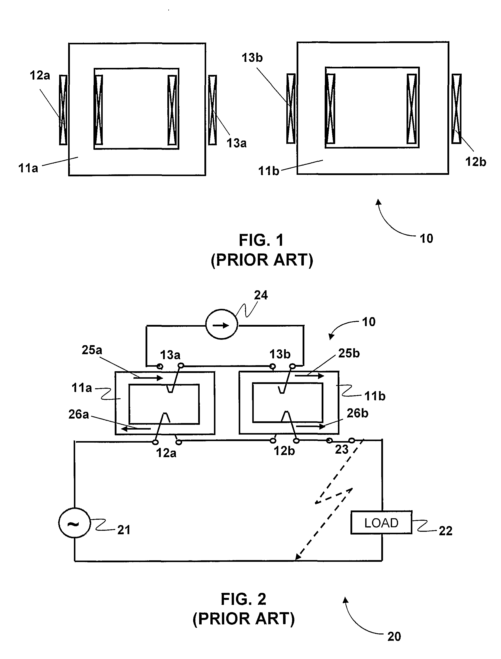
[0054]In order more fully to appreciate the benefits of the invention, it will be instructive first to consider a typical prior art single phase FCL. To this end, FIG. 1 shows pictorially a prior art saturated core single phase FCL 10 having a magnetic circuit comprising a pair of closed magnetic cores 11a and 11b each supporting a respective AC coil 12a and 12b. The cores further support a pair of DC superconducting bias coils 13a and 13b.
[0055]FIG. 2 shows schematically a circuit diagram of a system 20 showing the single phase FCL 10 in use. An AC supply 21, typically from the electric power grid, is connected to a load 22 via a circuit breaker 23. In series with the load 22 are connected the two AC coils 12a and 12b of the FCL 10. The...
PUM
Abstract
A current limiting device (30, 40, 50, 60) comprising for each phase of an AC supply a closed magnetic core (31) of reduced volume and mass having first and second pairs of opposing limbs (32a, 32b; 33a, 33b), and at least one AC coil (35a, 35b) enclosing opposing limbs (33a, 33b) of the magnetic core (31) and adapted for series connection with a load. A superconducting DC bias coil (34) encloses a limb) (32a, 32b) of the magnetic core (31) for saturating each of the opposing limbs (33a, 33b) in opposite directions by the bias coil (34). Under fault conditions, the AC flux in at least one limb counteracts the DC bias flux, bringing the limb out of saturation. Preferably, current is reduced in the DC bias coils thus bringing both opposing limbs of the core out of saturation.
Description
FIELD OF THE INVENTION[0001]This invention relates to superconducting current limiting devices for AC electric grid.REFERENCES[0002]In the following description, reference will be made to the following publications:[0003][1] B. P. Raju, K. C. Parton, T. C. Bartram, “A current limiting device using super-conducting d.c. bias: applications and prospects,”IEEE Transactions On Power Apparatus &Systems, vol. 101, pp. 3173-3177, 1982.[0004][2] J. X. Jin, S. X. Dou., C. Grantham, and D. Sutanto “Operating principle of a high T-c superconducting saturable magnetic core fault current limiter”. Physica C, 282, Part 4: p. 2643-2644, 1997.[0005][3] J. X. Jin, S. X. Dou., C. Cook, C. Grantham, M. Apperley, and T. Beals, “Magnetic saturable reactor type HTS fault current limiter for electrical application”. Physica C, 2000. 341-348: p. 2629-2630.[0006][4] V. Keilin, I. Kovalev, S. Kruglov, V. Stepanov, I. Shugaev, V. Shcherbakov, I. Akimov, D. Rakov, and A. Shikov, “Model of HTS three-phase satur...
Claims
Application Information
Patent Timeline
Application Date:The date an application was filed.
Publication Date:The date a patent or application was officially published.
First Publication Date:The earliest publication date of a patent with the same application number.
Issue Date:Publication date of the patent grant document.
PCT Entry Date:The Entry date of PCT National Phase.
Estimated Expiry Date:The statutory expiry date of a patent right according to the Patent Law, and it is the longest term of protection that the patent right can achieve without the termination of the patent right due to other reasons(Term extension factor has been taken into account ).
Invalid Date:Actual expiry date is based on effective date or publication date of legal transaction data of invalid patent.