Multiplexing schemes for ofdma

a multi-schema and multi-schema technology, applied in the field of multi-schema, can solve the problems of large signalling overhead, significant scheduling complexity and signalling overhead, and achieve the effect of improving reliability

Inactive Publication Date: 2009-01-22
APPLE INC
View PDF14 Cites 321 Cited by
  • Summary
  • Abstract
  • Description
  • Claims
  • Application Information

AI Technical Summary

Benefits of technology

[0052]According to a seventh aspect of the invention, there is provided a method of transmitting sub-packets within frames comprising: transmitting frames using OFDM, each frame occupying a plurality of OFDM symbols; for Some wireless stations, allocating resources over multiples of nominal frames; for wireless stations being allocated resources over multiples of nominal frames, combining multiple packets into composite packets, and allocating these composite packets with a larger number of retransmissions for improved reliability.

Problems solved by technology

While this approach allows adaptation to real time channel conditions, it incurs large signalling overhead.
This enables lower signalling overhead for retransmission, but can cause significant scheduling complexity and signalling overhead for the first transmission due to the irregular vacancies of resources that occurs since some resources need to be reserved for retransmissions that may not be necessary.

Method used


Image

  • Multiplexing schemes for ofdma
  • Multiplexing schemes for ofdma
  • Multiplexing schemes for ofdma

Examples


first example

[0381]In some embodiments, a first subset of users are fully persistent, and a second subset, possibly all remaining users, have a only their first allocation a persistent first allocation.

[0382]In an example of full persistent allocation using a combined bitmap, the users with full persistent allocation for all HARQ transmissions are designated as a special user group in the bitmap. The users' positions in bitmap could be all at the beginning, or distributed throughout the bitmap in some known way. In some embodiments, a separate bitmap is employed. The locations in the bitmap are known for all other users to see. In some embodiments, the number of the first subset is fixed, and in known locations, so that all users can tell which bits in the bitmap relate to full persistent resource allocations.

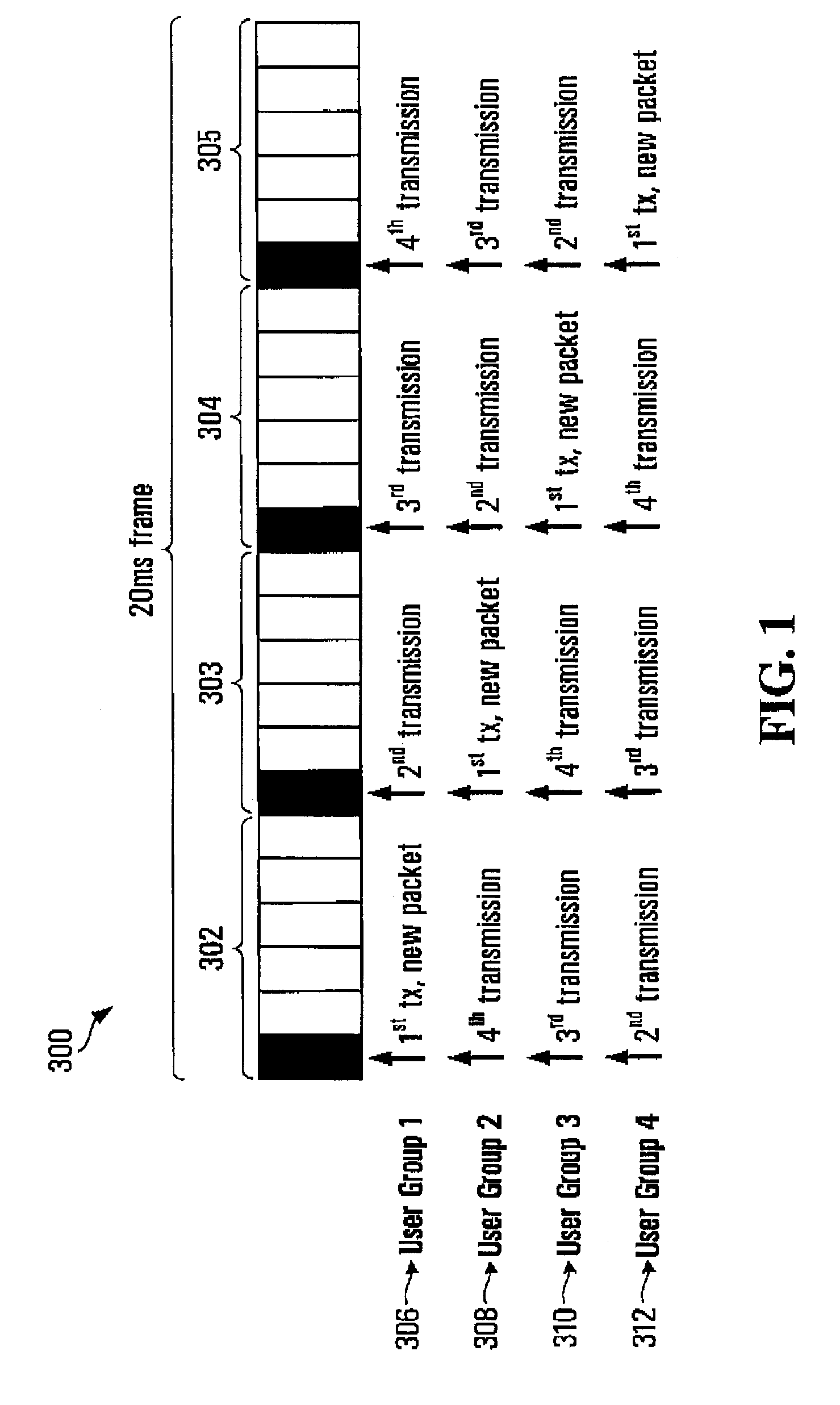
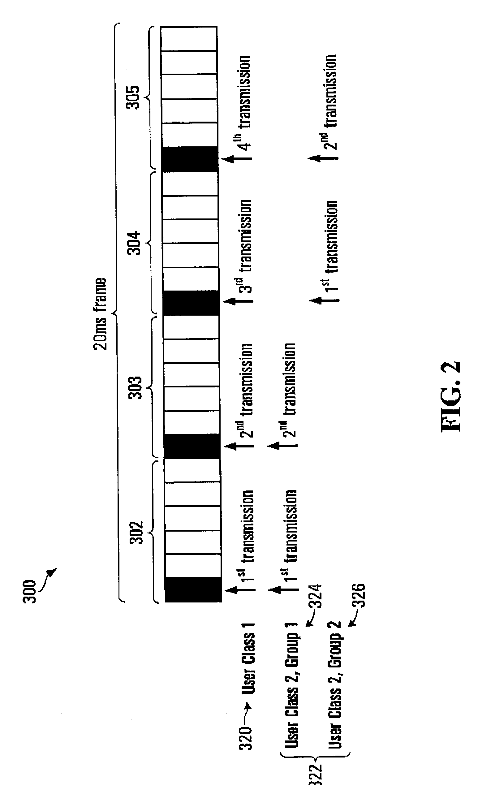
[0383]In some embodiments, the full persistent allocation users are further segmented into groups that have different HARQ sub-packet start points, as described for other embodiments above....

second example

[0388]In a second example of the use of a combined bitmap for full persistent users and persistent first transmission users, a cyclic shift within full persistent resources is employed.

[0389]More generally, for any of the embodiments described herein, a cyclic shift can be performed for any resource allocation, meaning that the location of a resource associated with particular signalling will move cyclically through the available resource. More generally still, for any of the embodiments described herein, an arbitrary shift of the resource allocation can occur, so long as the shift is known to both the transmitter and receiver.

[0390]In an example of full persistent allocation using a combined bitmap, the users with full persistent allocation for all HARQ transmissions are designated as a special user group in the bitmap. The users' positions in the bitmap could be all at the beginning, or distributed throughout the bitmap in some way. In some embodiments, a separate bitmap is employ...


PUM


Abstract

Methods and systems are provided for allocating resources including VoIP (voice over Internet Protocol) and Non-VoIP resources. In some embodiments, multiplexing schemes are provided for use with OFDMA (orthogonal frequency division multiplexing access) systems, for example for use in transmitting VoIP traffic, in some embodiments, various HARQ (Hybrid Automatic request) techniques are provided for use with OFDMA systems. In various embodiments, there are provided methods and systems for dealing with issuea such as Handling non-full rate vocoder frames, VoIP packet jitter handling, VoIP capacity increasing schemes, persistent and non-persistent assignment of resources in OFDMA systems.

Description

RELATED APPLICATIONS[0001]This application claims the benefit of U.S. Provisional Application Nos.[0002]60 / 805,670 filed Jun. 23, 2006,[0003]60 / 820,683 filed Jul. 28, 2009,[0004]60 / 822,018 filed Aug. 10, 2006,[0005]60 / 824,848 filed Sep. 7, 2006,[0006]60 / 825,360 filed Sep. 12, 2006,[0007]60 / 828,312, filed Oct. 5, 2006[0008]60 / 728,848 filed Oct. 21, 2005,[0009]60 / 820,705 filed Jul. 28, 2006,[0010]60 / 758,743 filed Jan. 13, 2006, and[0011]60 / 829,426 filed Oct. 12, 2006, which are all incorporated herein by reference.FIELD OF THE INVENTION[0012]The invention relates to multiplexing schemes for use with OFDMA (orthogonal frequency division multiplexing access) systems, for example for use in transmitting VoIP (voice over Internet Protocol) traffic.BACKGROUND OF THE INVENTION[0013]There are several proposals to 3GPP2 for OFDMA VoIP implementations, one of which defines numerology such that an OFDMA resource consisting of a set of 340 sub-carriers in frequency over OFDM symbol durations in ...

Claims


Application Information

Patent Timeline
Patent Type & Authority Applications(United States)
IPC IPC(8): H04W72/04H04L27/28
CPCH04L5/0064H04L29/06027H04L65/80H04L5/0007H04L5/0037H04L5/0046H04L1/0067H04L65/607H04L1/0013H04L5/0042H04L2001/0093H04L1/1614H04L1/1867H04L1/14H04L1/0025H04L65/70H04L65/1101
Inventor NOVAK, ROBERTZHANG, HANGVRZIC, SOPHIEFONG, MO-HANAU, KELVIN KAR-KINMA, JIANGLEIZHU, PELYINGTONG, WEN
Owner APPLE INC
Why Eureka
Try Eureka