Electrical plug connector

a technology of electrical plug connectors and plug connectors, which is applied in the direction of electrical apparatus, connection, coupling device connection, etc., can solve the problems of increasing complexity and thus the cost of production of corresponding electrical plug connectors, unable to reliably tell whether or not an led is illuminated, and production is relatively complex and costly, so as to reduce the transparency of thermoplastic materials, reduce costs, and produce as easily

Active Publication Date: 2009-01-22
IMF ELECTRONIC GMBH
View PDF10 Cites 27 Cited by
  • Summary
  • Abstract
  • Description
  • Claims
  • Application Information

AI Technical Summary

Benefits of technology

[0011]The present invention is therefore based on the object of providing an electrical plug connector that avoids the disadvantages mentioned above and furthermore can be produced as easily as possible, and thus at a lower cost. This object is achieved, wherein the housing is composed of a thermoplastic material, at least in the area of the light-emitting element, with the thermoplastic material having an additive that influences the transparency and color, and which reduces the transparency of the thermoplastic material. Contrary to the procedure that has been practiced until now in the prior art of using a highly transparent material at least in the area of the light-emitting element, the present invention now proposes that the transparency of the material be deliberately reduced. In this case, this is done by adding an additive to the thermoplastic material for production of the housing, thus advantageously reducing the color and hence the transparency of the housing.
[0012]In this case, a color concentrate with organic and / or inorganic dyes is preferably used as the additive, and is added to the thermoplastic material in the form of powder or granulate. The dyes preferably have a grey or black color, so that the complete housing also overall has a grey to black color. The proportion by weight of the additive can be less than 5%, preferably between 1% and 3%, and in particular about 2%, thus making it possible to reduce the transparency by about 60% to 80%, and preferably by about 70%.
[0013]As before, the coloring of the housing according to the invention makes it possible to tell whether an LED is illuminated from the outside through the housing, furthermore resulting in a considerable increase in contrast, so that the status of an LED can be seen well, even when the plug connector is subject to strong external incident light. In this case, the thermoplastic materials, in particular polyurethane, thermoplastic elastomer or polyvinyl chloride, can still be used as the basic material for the housing, so that the production process for the electrical plug connector can remain virtually unchanged.
[0014]According to one preferred embodiment of the invention, the housing of the electrical plug connector is composed entirely of the thermoplastic material, which is provided with the additive. The housing can thus still be produced in a single injection-moulding process. No sealing problems can occur at junctions between different housing parts. Furthermore, the use of a housing that is colored overall, has the advantage that the electronics circuit, which is arranged within the housing and / or is extrusion-coated by the thermoplastic material, can no longer be seen as clearly from the outside as would be the case with a “completely” transparent housing. Advantageously, a user's attention is no longer distracted to such a circuit, so that the user can concentrate on telling whether the LED is or is not illuminated. Preferably, the coloring of the housing is such that the housing is completely non-transparent and only the specific wavelength of the LED, when illuminated, can be seen from outside the housing.
[0019]The transparent cover, which is arranged above the LEDs, may in this case be used in particular for focusing and guidance of the light emitted from the LEDs to the symbols formed in the housing. The cover is in this case is preferably configured in the form of a shutter or aperature, such that only the light coming from the associated LED in each case passes through the two symbols. This ensures that, despite the physical proximity of the two LEDs within the housing, light passes only through the symbol associated with the respective LED when that LED is illuminated.

Problems solved by technology

The first variant has the disadvantage that, first of all, the production is relatively complex and costly since the various parts, e.g., the housing and cover, must be produced and connected to one another, for example, by adhesive bonding or ultrasound welding.
Furthermore, the two-part configuration means that sealing problems also can occur, so that, for applications in which the sealing of the housing is significant, the complexity and thus also the costs for production of a corresponding electrical plug connector can rise further.
For applications in which the electrical plug connector is subject to strong external incident light, there is a problem, however, in that it is often no longer reliably possible to tell whether or not an LED is illuminated.
Because of the transparent material that is used, it is also possible in particular in this case for reflections to occur of the light striking the plug connector from outside onto components arranged in the housing, wherein it is then virtually impossible to distinguish the reflected light from the light from the LED.

Method used


Image

  • Electrical plug connector
  • Electrical plug connector
  • Electrical plug connector

Examples


Embodiment Construction

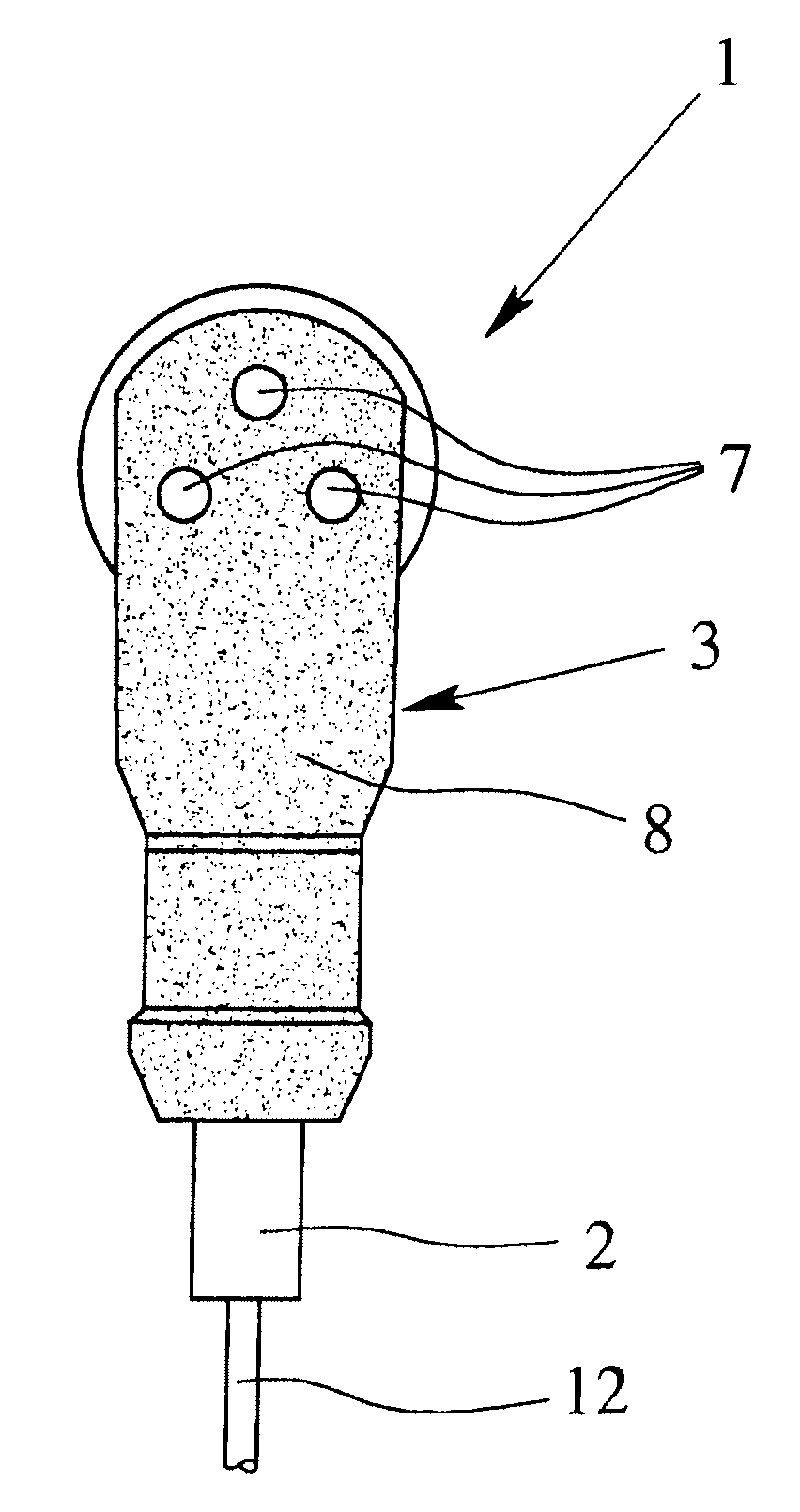
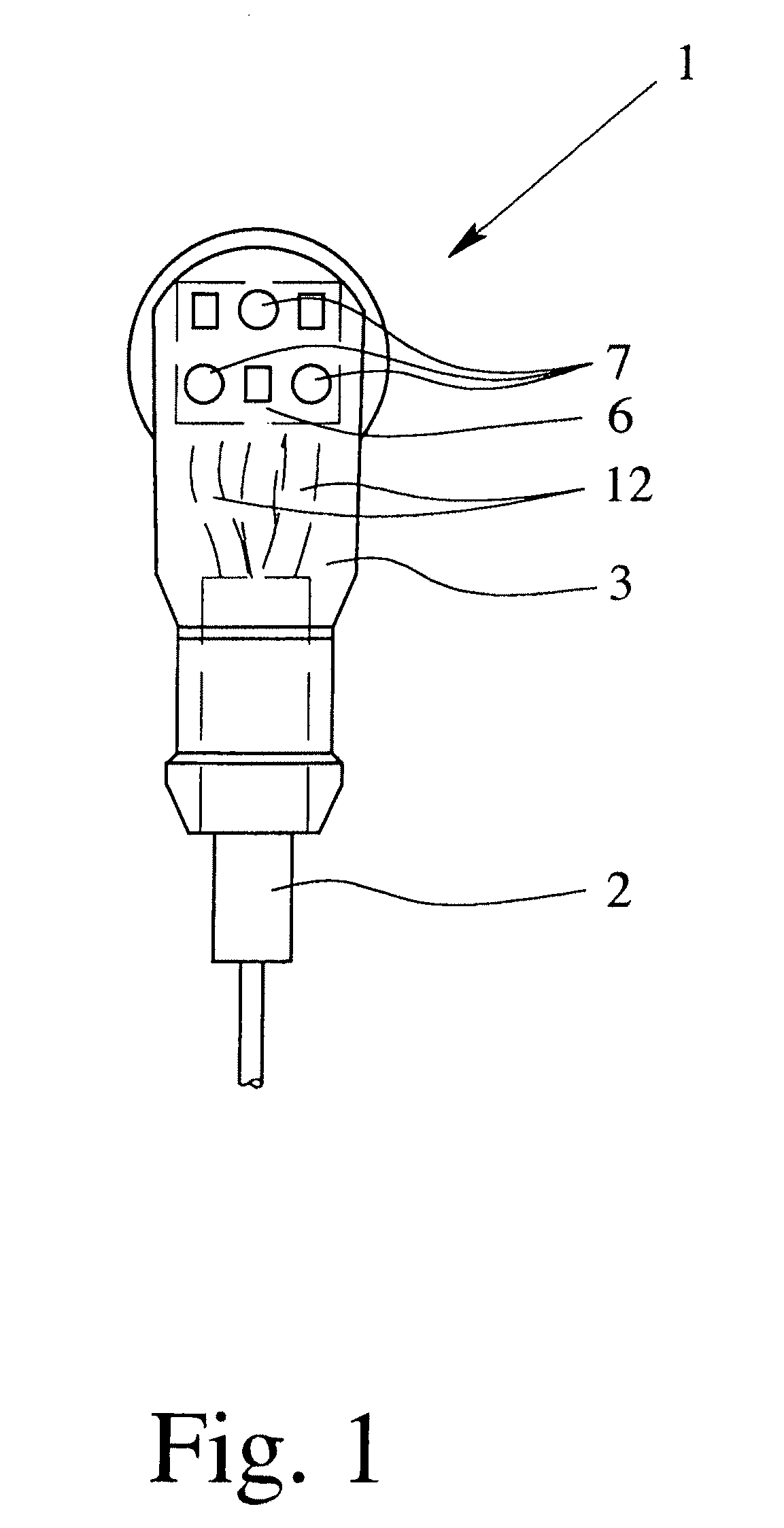
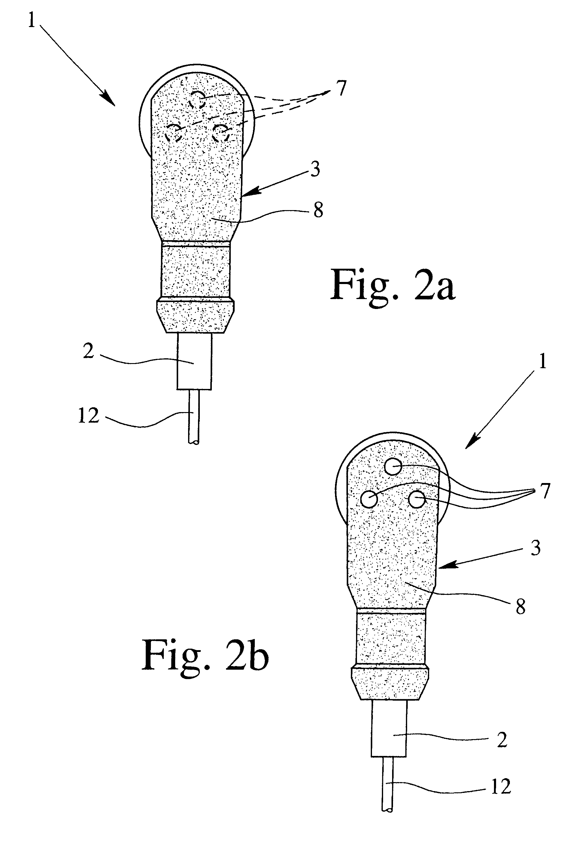
[0026]The figures show various exemplary embodiments of an electrical plug connector 1, withFIG. 1 showing an electrical plug connector 1 according to the prior art and FIGS. 2 to 4 showing two variants of an electrical plug connector 1 according to the invention. The electrical plug connectors 1 illustrated in FIGS. 1 to 3 are used for connection of an electrical cable 2 to an electronic apparatus, in particular a sensor, for example a proximity switch, a temperature sensor, a flow sensor, and the like.

[0027]The electrical plug connector 1 has a housing 3, a contact mount 5, which holds a plurality of contacts 4 and an electronics circuit 6 arranged in the housing 3. In this case, the electronics circuit 6 generally includes a printed circuit board on which, in addition to a number of electrical and electronic components, a plurality of LEDs 7, generally up to three LEDs 7, are arranged. The LEDs 7 are in this case used for status indication for the connected sensor. The electrical...


PUM


Abstract

An electrical plug connector for connection of an electrical cable (2) to an apparatus, such as a sensor or an actuator, includes a housing (3) having a contact mount (5) holding a variety of contacts (4), and an electronics circuit (6) having at least one light-emitting element, LED (7) and being electrically connected to the contacts (4). The status of whether the LED (7) is illuminated or not can be identified particularly well, even in the presence of strong external incident light, by the housing (3) being composed of a thermoplastic material, at least in the area of the LEDs (7), and including an additive (8) that influences transparency and color for reducing the transparency of the thermoplastic material.

Description

BACKGROUND OF THE INVENTION[0001]1. Field of Invention[0002]The invention relates to an electrical plug connector for connection of an electrical cable to an apparatus, and in particular to a sensor or an actuator, or for detachable connection of two electrical cables to one another, and having a housing, including a contact mount, which holds a variety of contacts, and an electronics circuit, which is arranged in the housing, with the electronics circuit having at least one light-emitting element, including an LED, and being electrically connected to the contacts.[0003]2. Description of Related Art[0004]Essentially, electrical plug connections are composed of two parts, the electrical plug connector and the mating plug connector. Electrical plug connections can either be used to connect an electrical cable to an electrical or electronic appliance, or to connect two cables to one another. In the first case, the mating plug connector is connected to the electrical housing, and in the...

Claims


Application Information

Patent Timeline
Patent Type & Authority Applications(United States)
IPC IPC(8): H01R13/717
CPCH01R13/465H01R13/7175H01R13/717H01R13/6691
Inventor MEHNERT, WOLFGANGANZER, GILBERT
Owner IMF ELECTRONIC GMBH
Why Eureka
Try Eureka