Fiber rendering apparatus

a fiber rendering and fiber technology, applied in the field of fiber rendering method and magnetic resonance imaging apparatus, can solve the problems of unnatural image, low fiber tracking reliability, and inability to accurately diagnos

Active Publication Date: 2005-05-12
GE MEDICAL SYST GLOBAL TECH CO LLC
View PDF9 Cites 30 Cited by
  • Summary
  • Abstract
  • Description
  • Claims
  • Application Information

AI Technical Summary

Benefits of technology

[0025] Thus, a fifth object of the present invention is to provide a fiber rendering method by which connectivity by fiber nerves between two sites that an operator specifies can be visually recognized.

Problems solved by technology

When the grid points regularly generated at Step P3 in FIG. 21 are defined as the tracking start points, the fiber density looks as if it suddenly decreases when the view direction is parallel to a direction of the grid point arrangement, because the nerve fibers passing through the tracking start points lining up in the view direction appear to overlap one another, leading to a problem that the image gives an unnatural impression.
The portion with considerably low fiber tracking reliability is, however, rendered in the same manner of display as that for rendering a portion with high reliability, and these portions cannot be distinguished, leading to the problem that this poses a hindrance to accurate diagnosis.
On the other hand, when the threshold at Step P9 in FIG. 21 is large, the fiber tracking is aborted before an end portion of a brain white matter fiber is reached, leading to a problem that fibers cannot be fully rendered.

Method used


Image

  • Fiber rendering apparatus
  • Fiber rendering apparatus
  • Fiber rendering apparatus

Examples


first embodiment

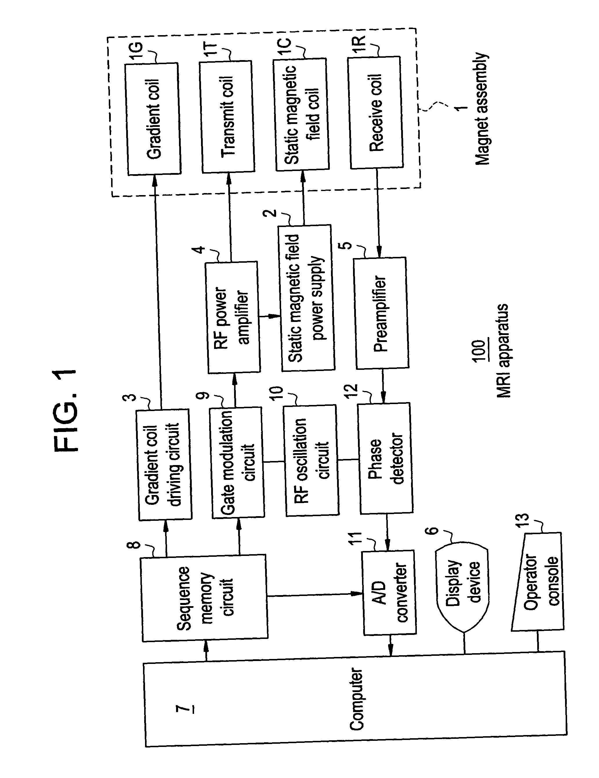
[0103]FIG. 1 is a block diagram showing an MRI apparatus in accordance with one embodiment of the present invention.

[0104] In the MRI apparatus 100, a magnet assembly 1 has a bore (cavity portion) for inserting therein a subject, and is provided, surrounding the bore, with a gradient coil (which comprises X-axis, Y-axis and Z-axis coils, and the combination thereof determines slice, warp and read axes) 1G for generating gradient magnetic fields, a transmit coil 1T for applying RF pulses for exciting spins of atomic nuclei within the subject, a receive coil 1R for detecting NMR signals from the subject, and a static magnetic field power supply 2 and static magnetic field coil 1C for generating a static magnetic field.

[0105] It should be noted that permanent magnets may be employed in place of the static magnetic field power supply 2 and static magnetic field coil 1C (superconductive coil).

[0106] The gradient coil 1G is connected to a gradient coil driving circuit 3. The transmit c...

second embodiment

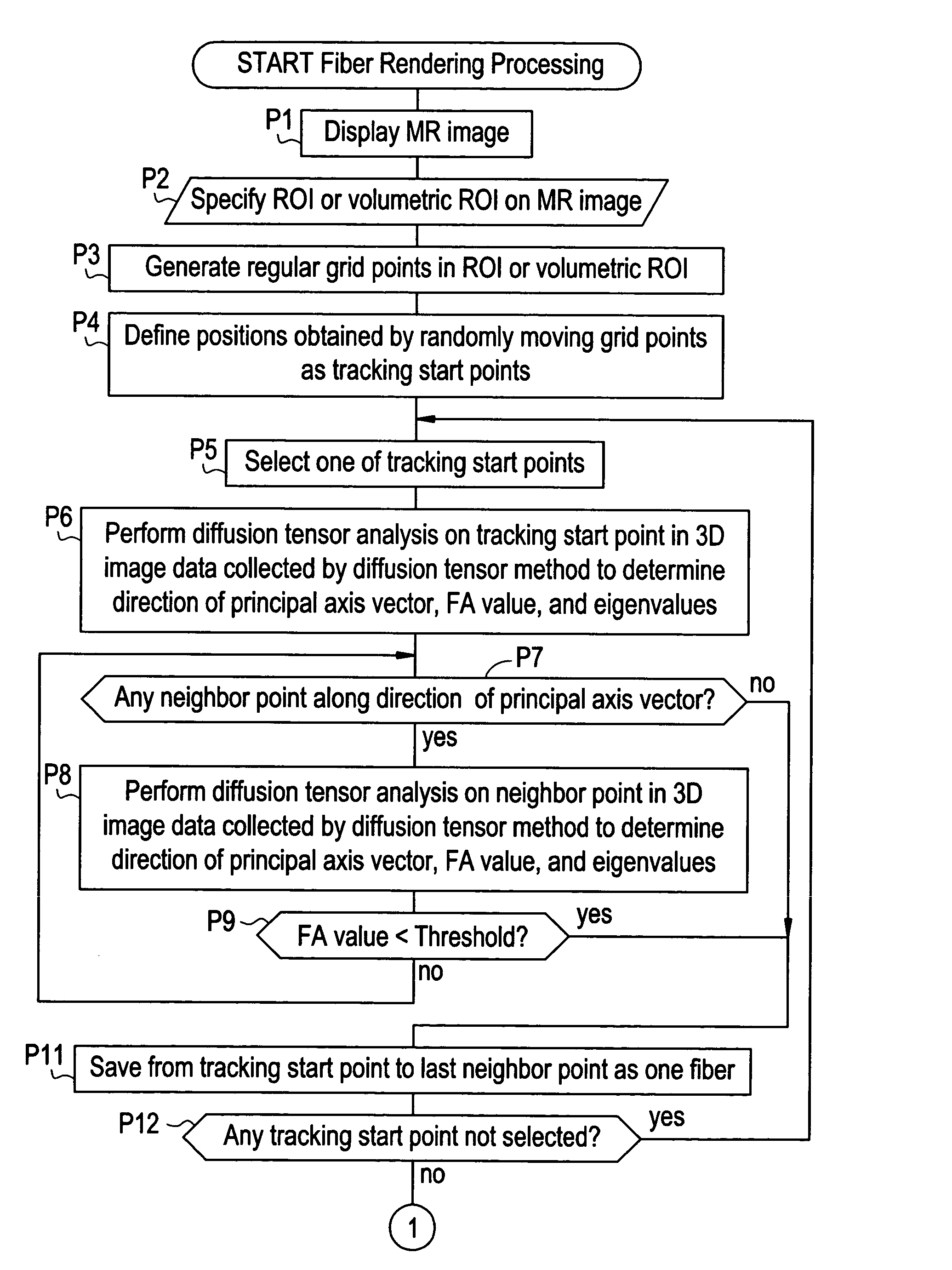
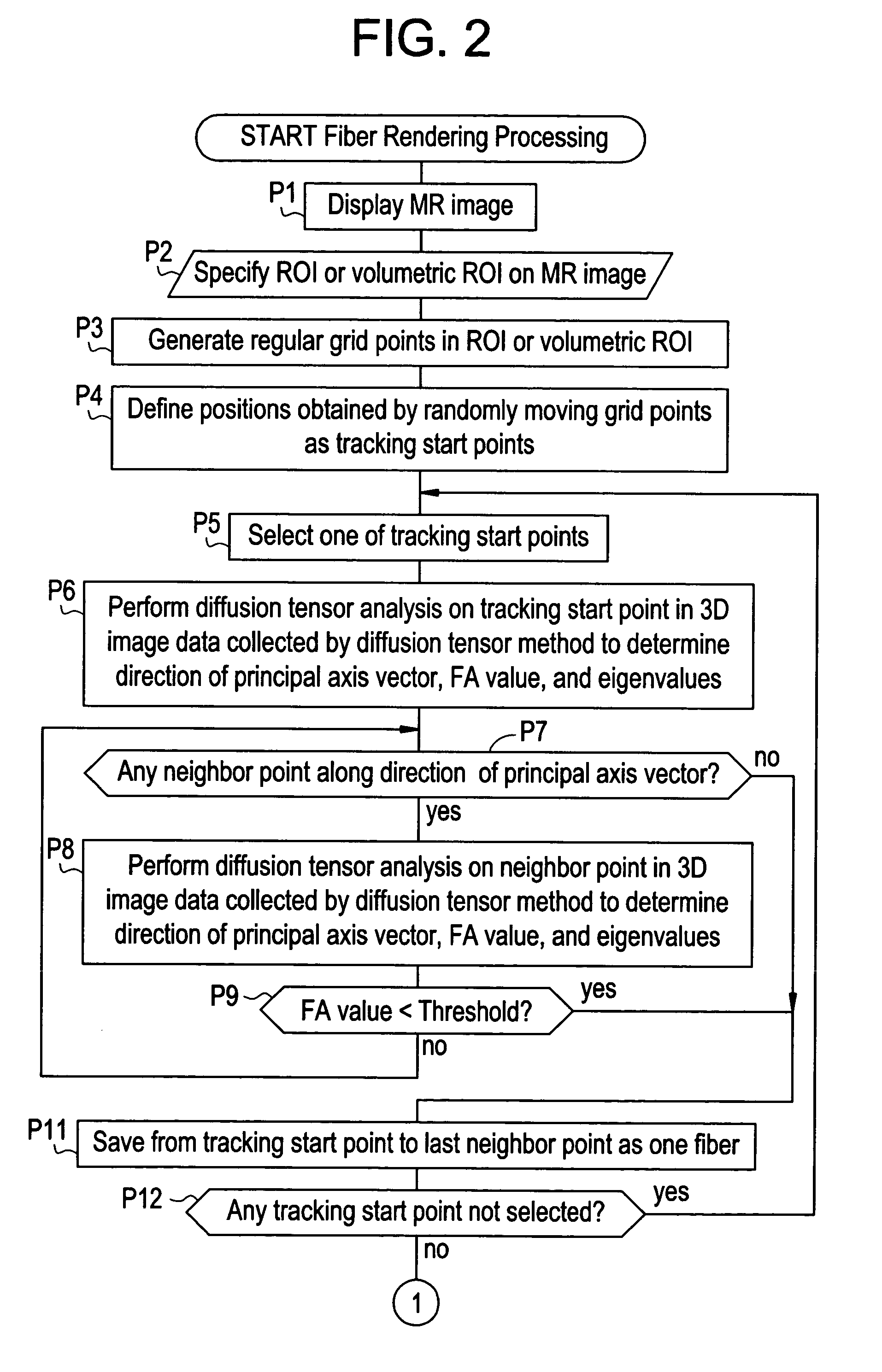
[0135]FIG. 10 is a flow chart showing fiber rendering processing by an MRI apparatus in accordance with a second embodiment.

[0136] At Step Q1, an MR image in an axial or oblique plane is produced from three-dimensional image data collected by a diffusion tensor method or another imaging method (T1- or T2-enhanced or the like) in the MRI apparatus, and the MR image is displayed.

[0137] At Step Q2, an operator specifies a two-dimensional region of interest R1 (or a three-dimensional volumetric region of interest) on a displayed MR image G1, as shown in FIG. 4.

[0138] At Step Q3, regular grid points g1, g2, g3, . . . are generated in the region of interest R1 (or in the volumetric region of interest), as shown in FIG. 5.

[0139] At Step Q4, points obtained by randomly moving the grid points g1, g2, g3, . . . in a two-dimensional (or three-dimensional) manner are defined as tracking start points S1, S2, S3, . . . , as shown in FIG. 6. Random numbers for the random moving can be generate...

third embodiment

[0158]FIG. 16 is a flow chart showing fiber rendering processing by an MRI apparatus in accordance with a third embodiment.

[0159] At Step Q1, an MR image in an axial or oblique plane is produced from three-dimensional image data collected by a diffusion tensor method or another imaging method (T1- or T2-enhanced or the like) in the MRI apparatus, and the MR image is displayed.

[0160] At Step Q2′, an operator specifies a two-dimensional start region of interest R1 (or a three-dimensional start volumetric region of interest) and a two-dimensional end region of interest R2 (or a three-dimensional end volumetric region of interest) on a displayed MR image G1, as shown in FIG. 19.

[0161] At Step Q3, regular grid points g1, g2, g3, . . . are generated in the start region of interest R1 (or in the start volumetric region of interest), as shown in FIG. 5.

[0162] At Step Q4, points obtained by randomly moving the grid points g1, g2, g3, . . . in a two-dimensional (or three-dimensional) mann...


PUM


Abstract

For the purpose of preventing a situation in which the fiber density looks as if it suddenly decreases in a specific view direction, a method comprises: specifying a region of interest R1 in MR image data collected by a diffusion tensor method; defining regular grid points in the region of interest R1; defining points obtained by randomly moving the grid points as tracking start points S1, S2, . . . ; performing diffusion tensor analysis on each tracking start point S1, S2, . . . in the image data to determine a direction of a principal axis vector; tracking a fiber by repeatedly selecting a neighbor point along the direction of the principal axis vector and performing diffusion tensor analysis on the neighbor point to determine the direction of the principal axis vector; and producing and displaying an image of the tracked fibers as viewed in a desired view direction.

Description

BACKGROUND OF THE INVENTION [0001] The present invention relates to a fiber rendering method and MRI (magnetic resonance imaging) apparatus, and more particularly to a method and MRI apparatus for properly rendering brain white matter fibers obtained by diffusion tensor imaging. [0002]FIG. 21 is a flow chart showing a conventional fiber rendering method. [0003] At Step P1, an MR image in an axial or oblique plane is produced from three-dimensional image data collected by a diffusion tensor method or another imaging method (T1- or T2-enhanced or the like) in an MRI apparatus, and the MR image is displayed. [0004] At Step P2, an operator specifies a two-dimensional region of interest R1 (or a three-dimensional volumetric region of interest) on a displayed MR image G1, as shown in FIG. 22. [0005] At Step P3′, regular grid points are generated in the region of interest R1 (or in the volumetric region of interest) as shown in FIG. 23, and they are defined as tracking start points S1, S2,...

Claims


Application Information

Patent Timeline
Patent Type & Authority Applications(United States)
IPC IPC(8): G01R33/54A61B5/055G01R33/563G06T5/00
CPCG01R33/56341G06T7/0012G06T7/0083G06T2207/30016G06T2207/20021G06T2207/20104G06T2207/20136G06T2207/10092G06T7/12G06T7/181
Inventor MASUTANI, YOSHITAKAABE, OSAMUAOKI, SHIGEKIKABASAWA, HIROYUKI
Owner GE MEDICAL SYST GLOBAL TECH CO LLC
Why Eureka
Try Eureka