Vehicle Control Device

a control device and vehicle technology, applied in underwater vessels, non-deflectable wheel steering, brake components, etc., can solve the problems of difficult technique, large discrepancy between the response characteristic and the response characteristic of the state amount of the actual vehicle and the required manipulated variable of the actuator device for making the state amount of the actual vehicle follow the state amount on the dynamic characteristic model

Active Publication Date: 2009-01-22
HONDA MOTOR CO LTD
View PDF1 Cites 14 Cited by
  • Summary
  • Abstract
  • Description
  • Claims
  • Application Information

AI Technical Summary

Benefits of technology

[0031]According to the fifth invention, the relationship between the steady-state value of a drive manipulated variable when the manipulated variable of drive manipulation is changed in steps and the steady-state value of the value of each type of state amount of the model state amount vector, that is, the steady-state characteristic of the vehicle model, is maintained to be constant even if the value of a parameter of the vehicle model is variably set (independently of a change in the value of the parameter). Therefore, the steady-state characteristic of the vehicle model can be turned into a characteristic that is substantially equivalent to the steady-state characteristic of the actual vehicle (more precisely, the relationship between the steady-state valu

Problems solved by technology

Nevertheless, it has been difficult for the technique disclosed in the aforesaid patent documents 1 and 2 to fully satisfy the above requirement for the following reason.
Hence, if the response characteristic of a dynamic characteristic model of a vehicle is set to a characteristic with a high attenuation property, such as a critical braking or over-braking characteristic (non-oscillatory characteristic), independently of the traveling velocity of the actual vehicle (at an arbitrary traveling velocity) according to the technique disclosed in patent documents 1 and 2, then there will be a significant discrepancy between the response characteristic of a state amount of a vehicle on the dynamic characteristic model and the response characteris

Method used


Image

  • Vehicle Control Device
  • Vehicle Control Device
  • Vehicle Control Device

Examples


first embodiment

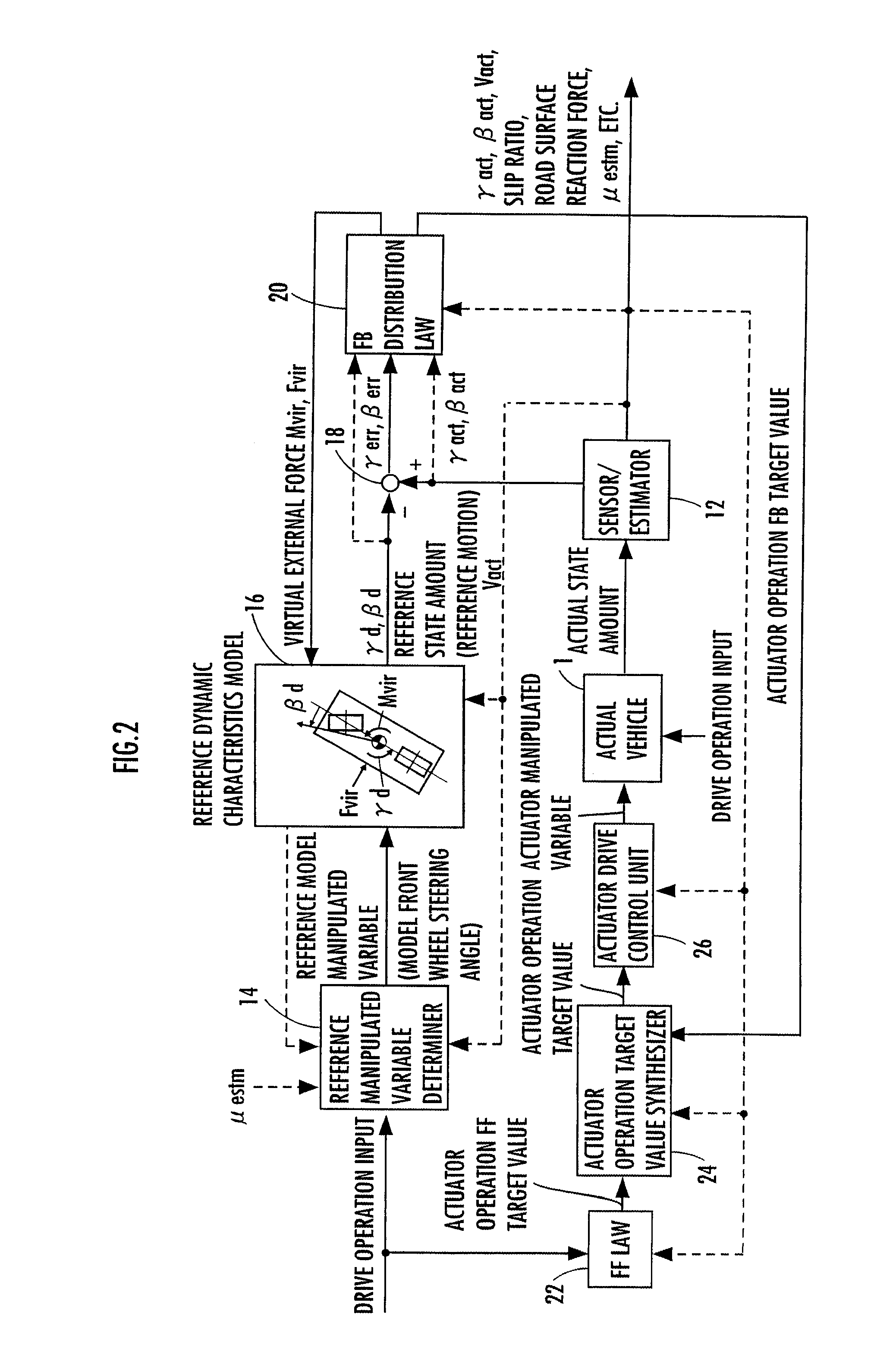
[0063]The control processing by a controller 10 in a first embodiment will now be schematically described with reference to FIG. 2. FIG. 2 is a functional block diagram illustrating an overview of the entire control processing function of the controller 10. In the description from now on, a real vehicle 1 will be referred to as an actual vehicle 1.

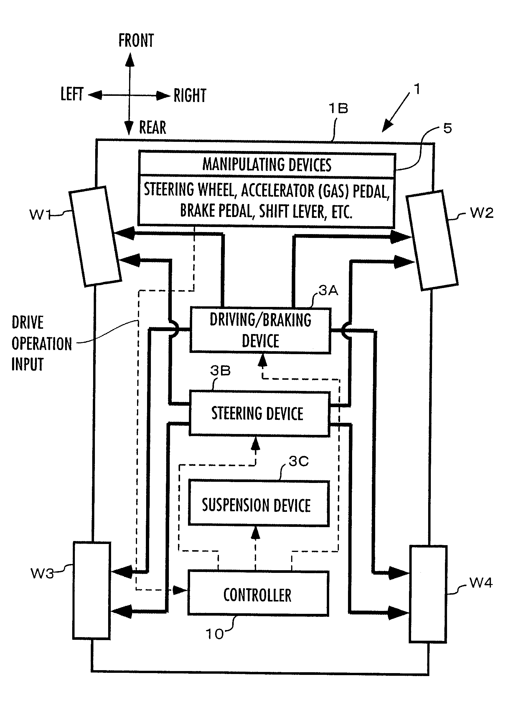
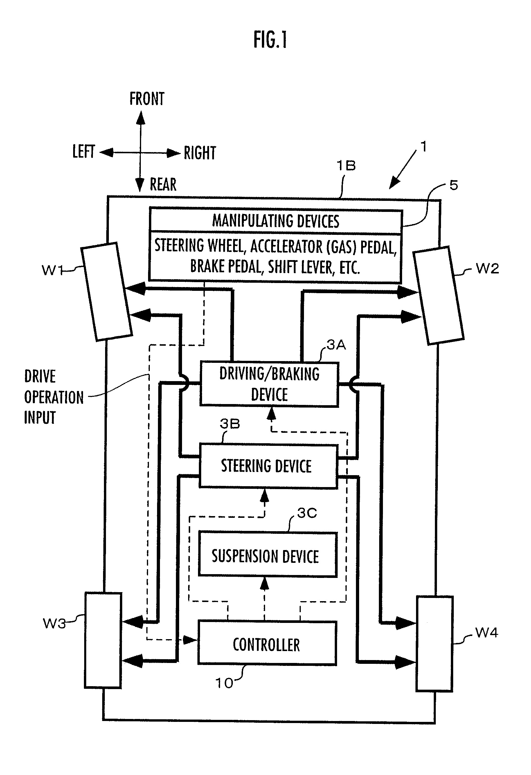
[0064]The portion excluding the actual vehicle 1 in FIG. 2 (more precisely, the portion excluding the actual vehicle 1 and sensors included in a sensor / estimator 12, which will be discussed later) corresponds to the primary control processing function of the controller 10. The actual vehicle 1 in FIG. 2 is provided with the driving / braking device 3A, the steering device 3B, and the suspension device 3C described above.

[0065]As illustrated, the controller 10 is equipped with, as its main processing function components, the sensor / estimator 12, a reference manipulated variable determiner 14, a reference dynamic characteristic model 16, a sub...

second embodiment

[0379]The following will describe a second embodiment of the present invention. The present embodiment differs from the aforesaid first embodiment only in the characteristics adjusting matrix K for adjusting the transient response characteristic of a model vehicle. Hence, the explanation will be focused mainly on the different aspect, and the explanation of the same construction and the same processing as those in the first embodiment will be omitted.

[0380]The aforesaid first embodiment has shown an example wherein k2 out of the model characteristics adjusting parameters k1 and k2, which are the diagonal components of the characteristic adjusting matrix K of the expression 01, has been variably set according to the traveling velocity Vact (=Vd) and k1 has been fixed to “1” in order to enhance the attenuation properties of the state amounts γd and βd of the model vehicle based on stepped changes in the steering angle θh.

[0381]In contrast to this, according to the present embodiment, ...

third embodiment

[0387]A third embodiment of the present invention will now be described. The present embodiment differs from the aforesaid first embodiment or the second embodiment only in the characteristics adjusting matrix K for adjusting the transient response characteristic of a model vehicle. Hence, the explanation will be focused mainly on the different aspect, and the explanation of the same construction and the same processing as those in the first embodiment or the second embodiment will be omitted.

[0388]In the first embodiment and the second embodiment, only one of the model characteristics adjusting parameters k1 and k2 of the characteristics adjusting matrix K of the aforesaid expression 01 has been variably set in order to enhance the attenuation properties of the state amounts βd and γd of the model vehicle based on stepped changes in the steering angle θh. In this case, if the traveling velocity Vact(=Vd) is higher than the critical braking velocity Vd_critical, then the absolute va...


PUM


Abstract

An actual vehicle actuator operation control input and a model operation control input are determined by an FB distribution law such that the difference between a reference state amount determined in a vehicle model and an actual state amount of an actual vehicle approximates zero, and then an actuator device of the actual vehicle and the vehicle model are operated on the basis of the control inputs. The value of a parameter of the vehicle model is set according to an actual vehicle motional state such that the attenuation property of a reference state amount when a drive manipulated variable is changed is higher than the attenuation property of an actual state amount. Accordingly, the actual vehicle actuator device is properly controlled independently of an actual vehicle motional state such that a state amount related to an actual vehicle motion approximates a vehicle state amount on a dynamic characteristic model.

Description

TECHNICAL FIELD[0001]The present invention relates to a control device of a vehicle having a plurality of wheels, such as an automobile (engine automobile), a hybrid car, and a two-wheeled motor vehicle.BACKGROUND ART[0002]Hitherto, there has been known a technique for controlling an actuator device provided in an actual vehicle, whereby a model representing the dynamic characteristics of a vehicle is used to set the target values of the motional state amounts, such as a yaw rate and a lateral velocity, of a vehicle, and then an actual device provided in an actual vehicle is controlled such that the state amounts of the actual vehicle follow the target values, as disclosed in, for example, Japanese Patent Application Laid-Open No. H11-91608 (hereinafter referred to as patent document 1) and Japanese Patent Application Laid-Open No. 2000-15938 (hereinafter referred to as patent document 2).[0003]According to the technique disclosed in these patent documents 1 and 2, a target yaw rate...

Claims


Application Information

Patent Timeline
IPC IPC(8): B60T8/58B60W10/00B60W10/04B60W10/06B60W10/18B60W10/184B60W10/20B60W10/22B60W30/00B60W30/02B60W50/06B62D6/00B62D101/00B62D103/00B62D111/00B62D113/00B62D137/00
CPCB60T8/17552B60T2230/02B60T2260/02B60T2270/86B60W10/04B62D6/003B60W10/18B60W50/06B60W2050/0028B60W2050/0033B62D6/002B60W10/12B60W40/10
Inventor TAKENAKA, TORUKONO, HIROSHITOYOSHIMA, TAKAYUKIURABE, HIROYUKI
Owner HONDA MOTOR CO LTD
Why Eureka
Try Eureka