Eureka AIR delivers breakthrough ideas for toughest innovation challenges, trusted by R&D personnel around the world.

Method for spray-forming melts of glass and glass-ceramic compositions

a technology of glass and glassceramic compositions, applied in glass reforming apparatus, glass making apparatus, manufacturing tools, etc., can solve the problems of complex arrangements of processes and systems

Inactive Publication Date: 2009-01-29
SCHOTT CORP
View PDF22 Cites 25 Cited by
  • Summary
  • Abstract
  • Description
  • Claims
  • Application Information

AI Technical Summary

Benefits of technology

[0005]While the known processes and systems provide for formation of solid particles through the use of ultrasonic shockwaves, the resultant particles can vary widely in size distribution. The formation of glass and glass ceramic particles having a controlled particle size distribution is important for processes which utilize such materials as precursors, such as in the preparation of opto-ceramic elements, filter media, and catalysts supports. Thus, the present invention is directed to a method and an apparatus for providing solids particles, especially glass and glass ceramic particles, by subjecting a stream of molten material to ultrasonic shock waves, whereby the size distribution of the resultant particles can be easily controlled.

Problems solved by technology

Furthermore, previously disclosed processes and systems often require complex arrangements to heat the melt delivery tube during operation, such as by injecting pressurized preheated gas, in order to prevent freezing of the melt discharge outlet.

Method used


Image

  • Method for spray-forming melts of glass and glass-ceramic compositions
  • Method for spray-forming melts of glass and glass-ceramic compositions
  • Method for spray-forming melts of glass and glass-ceramic compositions

Examples


example 1

Spraytest of Laser Glass LG-810

[0044]The laserglass LG-810 cullet was melted at a temperature of 1000° C. in a gas-heated 100 ml-crucible made out of high-temperature steel, and supplied to the spray-forming apparatus through a stainless-steel pipe with 5 mm diameter. Compressed air provided by a diesel compressor (AirMan 185CFM) at a sustained pressure of 8 bar and a peak flow rate of 180 SCFM was supplied to Gas Inlet 1 and Gas Inlet 2. The composition of the Nd-doped fluorophosphate laser glass LG-810 developed for high-energy laser applications at 1060 nm is as follows (see: Lee Cook and Karl-Heinz Mader, “Ultraviolet Transmission Characteristics of a Fluorophosphate Laser Glass”, Journal of The American Ceramic Society, Vol. 65, No. 5, December 1982):

CompoundWeight %P2O59.69AlF333.17NaF5.43KF3.62MgF25.83CaF230.45SrF28.82LaF32.00NdF32.00

After establishing flow, the spray-forming of the molten material was completed in less than 5 seconds. The resultant product was a mixture of ...

example 2

Spraytest of a Borosilicate Glass

[0045]The borosilicate glass was molten from cullet at a temperature of 1550° C. in an inductively heated 100 ml-crucible made out of a platinum-iridium alloy, and supplied to the spray-forming apparatus through a platinum-iridium alloy pipe with 5 mm diameter. Compressed air provided by a diesel compressor (AirMan 185 CFM) at a peak pressure of 8 bar and a peak flow rate of 180 SCFM was supplied to Gas Inlet 1 and Gas Inlet 2. The composition of the borosilicate glass was as follows:

OxideWeight %Na2O6.70B2O328.95SiO264.35

After establishing flow, the spray-forming of the molten material was completed in less than 5 seconds. The resultant product was a mixture of fibers and spherical particles. See FIG. 8. Due to the limited amount of glass supplied no attempt was made to separate the fiber generated during startup from the particulate produced towards the end of the run. The particulate obtained was characterized using optical microscopy, and consist...


PUM

PropertyMeasurementUnit
Temperatureaaaaaaaaaa

Abstract

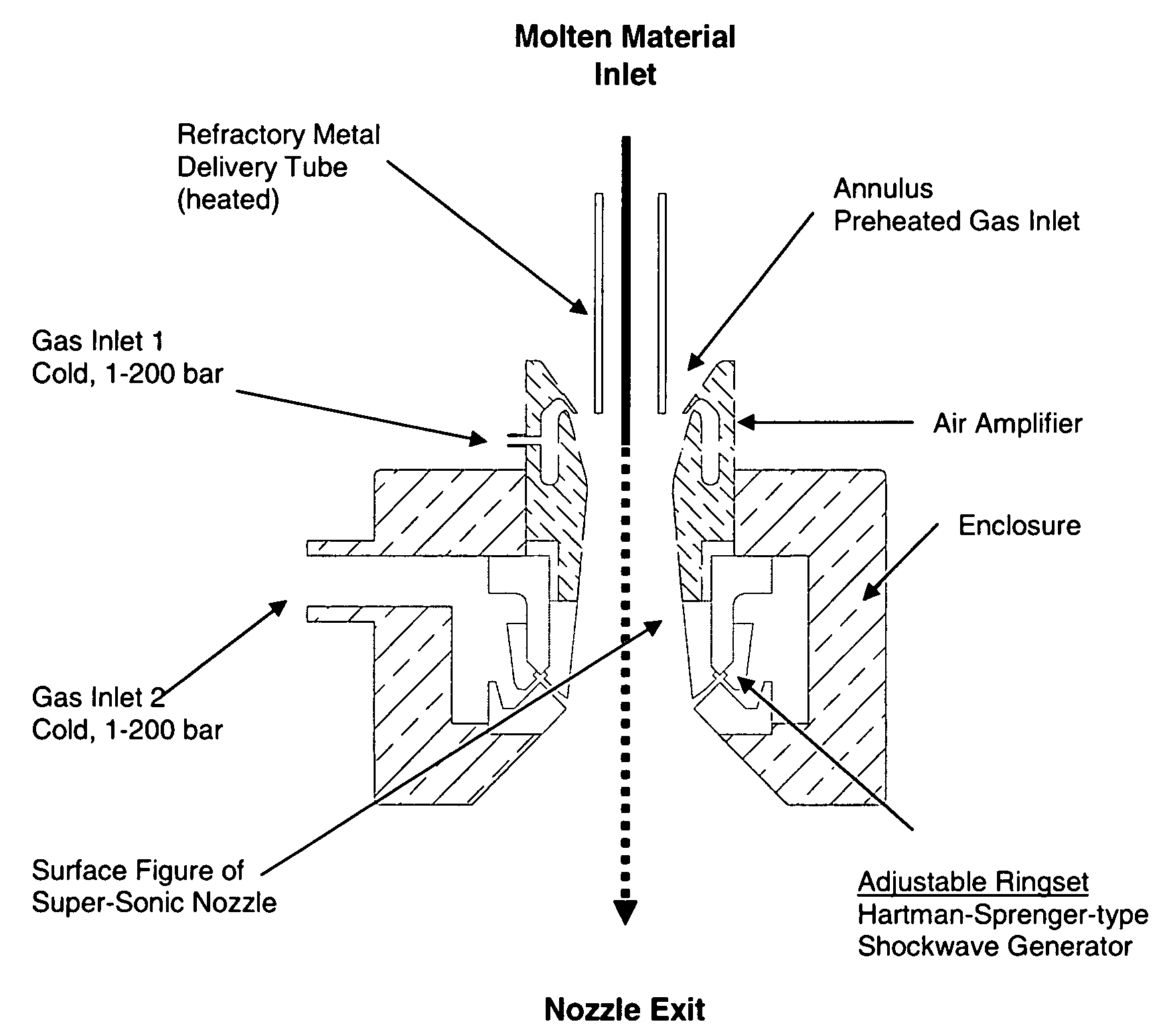
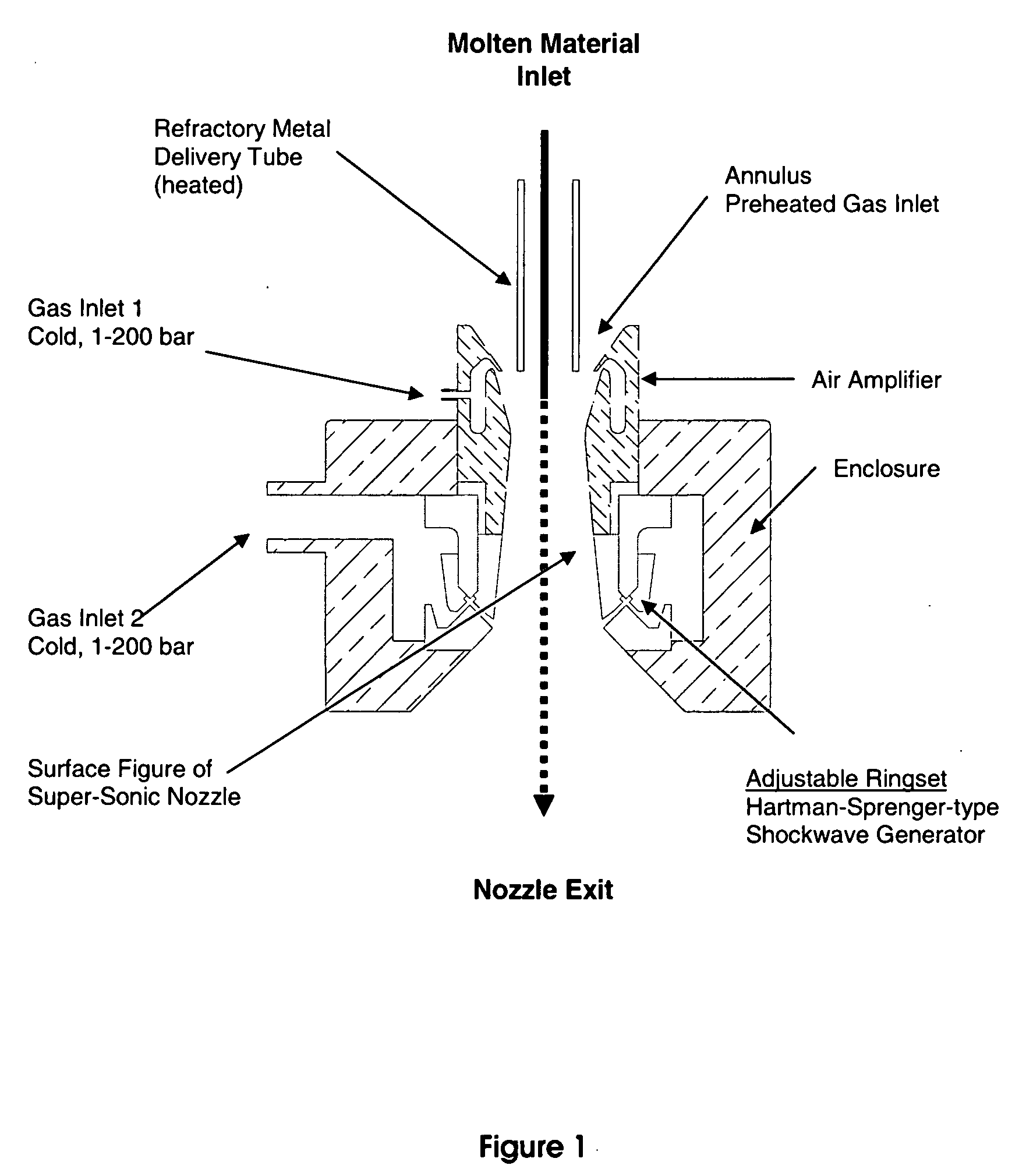
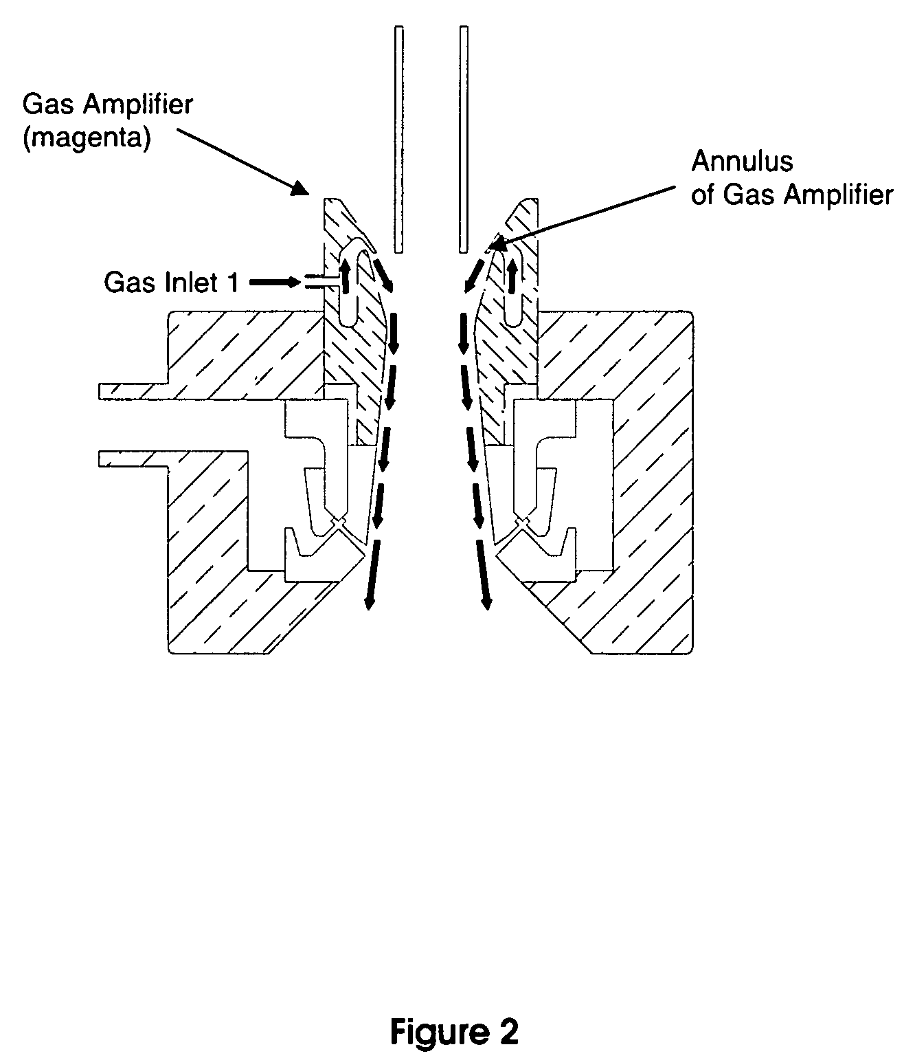
The invention relates to a process and apparatus for forming a particulate composition, especially a particle glass composition, through the use of shock waves. A nozzle element is utilized having inlets for introduction of cold and heated gas and a delivery tube for introducing molten material. Through the introduction of the cold and heated gases, droplets are formed from a molten stream, a cone-shaped standing shock wave is formed, and shock waves are formed via a modified Hartmann-Sprenger chamber, the shock waves impinging on the droplet stream to break up the larger droplets.

Description

[0001]The invention relates to a method and apparatus for preparing particulates from melts of glass or glass-ceramic compositions by spray-forming. In particular, the invention relates to a method and apparatus for preparing glass compositions of small particles, with narrow size distribution, in bulk quantities (>1 kg / min).BACKGROUND OF THE INVENTION [0002]There are numerous known methods for spraying molten material (mostly metals and polymers) to obtain particulate powders, such as spherical powders, having a defined size.[0003]U.S. Pat. No. 2,997,245 discloses an apparatus for pulverizing and / or decomposing solid as well as molten materials. One embodiment of the apparatus comprises a crucible, which contains molten material, and is positioned above a system of annular resonator chambers resembling a Hartmann-Sprenger chamber. Compressed gas streams through an annulus against an edge belonging to a first annular resonator chamber, and then into a second annular resonator cha...

Claims


Application Information

Patent Timeline
IPC IPC(8): C03B5/23C03B37/00
CPCB05B7/045B22F9/082B22F2009/084B22F2009/088C03B19/102B22F2999/00B22F2202/01
Inventor WEINHOLD, CARSTENYUHAS, DAVID JOHN
Owner SCHOTT CORP
Why Eureka
Eureka Blog
Learn More