Apparatus for Forming Layered Object

a technology of layered objects and forming apparatuses, which is applied in the direction of butter manufacturing, additive manufacturing with solid and fluid, brackets, etc., can solve the problems of limiting the improvement of manufacturing efficiency and productivity, modifying operations that need further skill, and omitting or simplifying surface smoothing treatment, so as to improve the adaptability to the mucosal surface in the mouth, the effect of reducing the steps due to layering and minute irregularities due to powder

Inactive Publication Date: 2009-01-29
SHOFU INC
View PDF10 Cites 97 Cited by
  • Summary
  • Abstract
  • Description
  • Claims
  • Application Information

AI Technical Summary

Benefits of technology

[0023]In accordance with the present invention, since the liquid is applied first to the base, the surface of the three-dimensional structure that has contacted the base truly reflects the surface shape of the base, so that the steps due to layering and minute irregularities due to powder can be reduced. Therefore, it is possible to achieve a three-dimensional structure with a smooth surface. As a result, the surface smoothing treatment can be omitted or simplified.
[0024]For example, in the case where a partial denture or a complete denture is produced, since the adaptability to the mucosal surface in the mouth improves considerably, the adjustment work at the time when a patient puts the denture in his / her mouth can be reduced greatly. Thus, it is possible to reduce the burden on the patient and the labor and working time of a dentist.
[0025]Also, a large number of processes that have been performed conventionally by a dental technician when producing a denture can be simplified greatly.
[0026]Furthermore, since the adaptability of the denture to the mucosal surface improves, it becomes possible to reduce the frequency at which the denture must be remade because of its poor adaptability.
[0027]Also, since the adaptability of the denture to the mucosal surface improves and the variation in adaptability according to different workers decreases, it becomes less necessary for a patient to use a denture stabilizer. Consequently, the occlusal vertical dimension is consistent with that at the time of designing the denture, so that an occlusal interference or an anomaly of a temporomandibular joint, which is caused by variations in the occlusal vertical dimension due to the use of the denture stabilizer, can be made less likely to occur.
[0028]Moreover, since it is possible to reduce the period from the time when a denture becomes necessary until a patient actually puts on the denture, the time during which the patient feels inconvenience until the completion of the denture can be shortened.

Problems solved by technology

Accordingly, it is very laborious and time-consuming to manufacture the dental structural materials, so that there is a limit to the improvement of manufacturing efficiency and productivity.
Also, since errors are inevitable due to several repetitions of mold making and casting processes, final products sometimes have unsatisfactory adaptability and color tones.
In order to solve these problems, adjusting and modifying operations that need further skill, trouble and time have to be undertaken.

Method used


Image

  • Apparatus for Forming Layered Object
  • Apparatus for Forming Layered Object
  • Apparatus for Forming Layered Object

Examples


embodiment 1

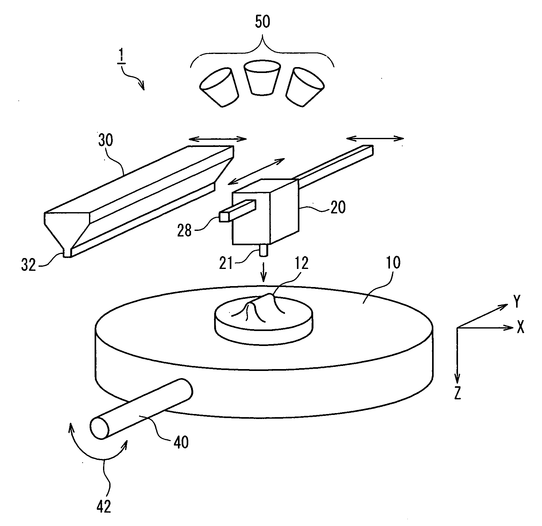
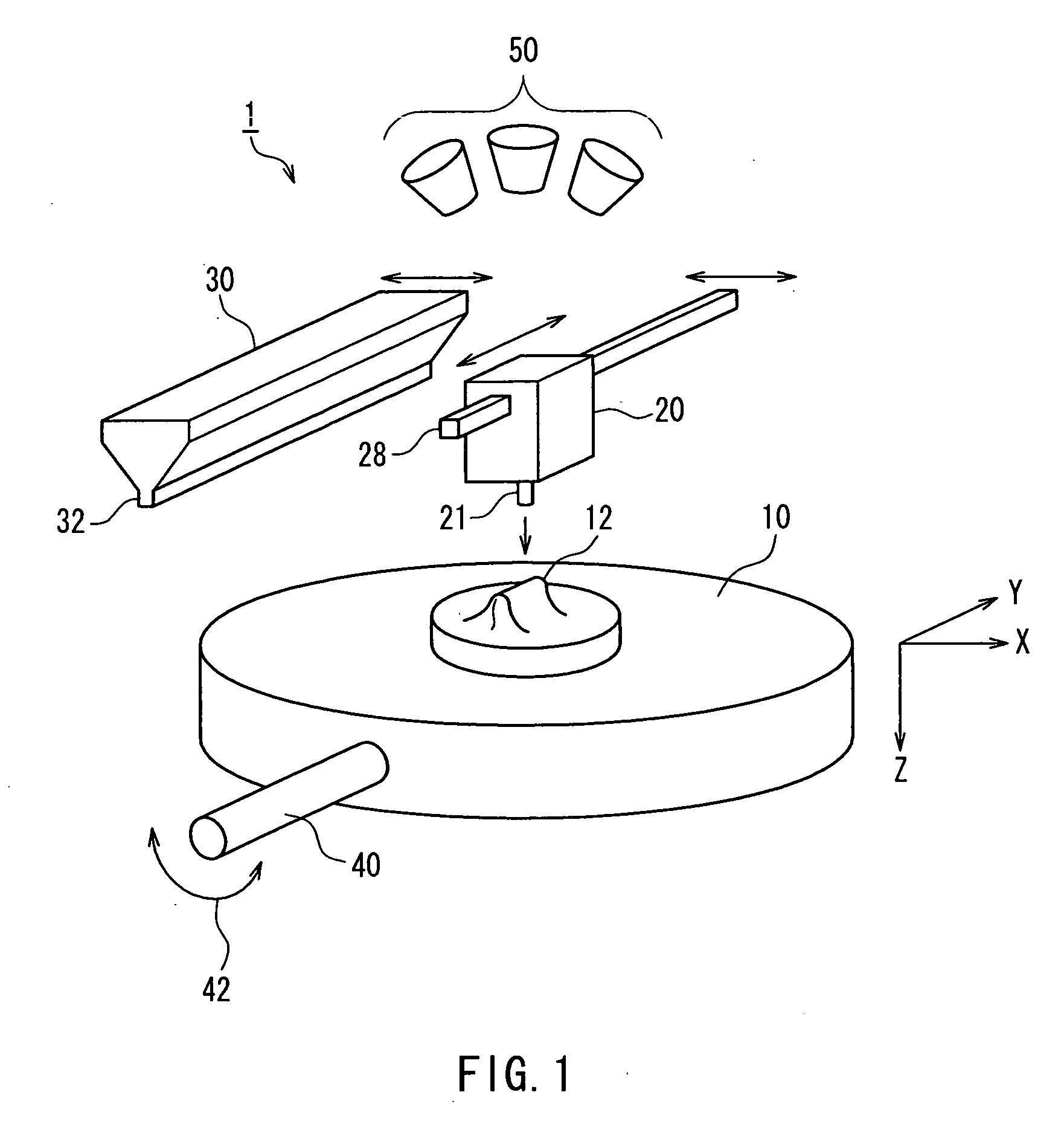
[0095]FIG. 1 is a perspective view showing a schematic configuration of a layered-object forming apparatus 1 according to Embodiment 1 of the present invention. As shown in this figure, horizontal axes that are perpendicular to each other are indicated by an X axis and a Y axis, and a vertical axis is indicated by a Z axis.

[0096]A base 12 is held on a forming table (a holding mechanism) 10. A three-dimensional structure is layered and formed on the base 12. One end of an arm 40 whose longitudinal direction corresponds to a Y-axis direction is coupled to the forming table 10, and the other end of the arm 40 is connected to a rotation driving mechanism, which is not shown in the figure. The rotation driving mechanism rotates the arm 40 in directions indicated by arrows 42 so as to flip the forming table 10.

[0097]A liquid feeder (a liquid applying device) 20 delivers a liquid from above the base 12 and allows the liquid to fall. The liquid feeder 20 moves in the Y-axis direction by a u...

embodiment 2

[0178]FIG. 4 is a perspective view showing a schematic configuration of a layered-object forming apparatus 2 according to Embodiment 2 of the present invention. Constituent elements that are the same as those in FIG. 1 are assigned the same reference numerals, and the detailed description thereof will be omitted.

[0179]The following description mainly is directed to points of Embodiment 2 that are different from Embodiment 1.

[0180]The layered-object forming apparatus 2 according to Embodiment 2 has an air nozzle 70 that ejects a gas 72 toward the base 12 on the forming table 10, instead of the arm 40 of the layered-object forming apparatus 1 according to Embodiment 1 for flipping the forming table 10.

[0181]In order to remove surplus powder that has not been consolidated by the liquid, the forming table 10 has been flipped so as to allow the powder to fall as shown in FIG. 3C in Embodiment 1. In contrast, in Embodiment 2, the gas 72 is ejected from the air nozzle 70 toward the base 12...

embodiment 3

[0186]FIG. 5 is a perspective view showing a schematic configuration of a layered-object forming apparatus 3 according to Embodiment 3 of the present invention. Constituent elements that are the same as those in FIG. 1 are assigned the same reference numerals, and the detailed description thereof will be omitted.

[0187]The following description mainly is directed to points of Embodiment 3 that are different from Embodiment 1.

[0188]The layered-object forming apparatus 3 according to Embodiment 3 has a suction nozzle 80 that sucks an atmosphere 82 surrounding the base 12 on the forming table 10, instead of the arm 40 of the layered-object forming apparatus 1 according to Embodiment 1 for flipping the forming table 10.

[0189]In order to remove surplus powder that has not been consolidated by the liquid, the forming table 10 has been flipped so as to allow the powder to fall as shown in FIG. 3C in Embodiment 1. In contrast, in Embodiment 3, the surplus powder together with the atmosphere ...


PUM

PropertyMeasurementUnit
grain sizeaaaaaaaaaa

Abstract

A layered-object forming apparatus (1) includes a holding mechanism (10) that holds a base (12), a liquid applying device (20) that applies a liquid to a predetermined position from above the base, a powder applying device (30) that allows a powder to fall from above the base, and a powder removing device that removes an unconsolidated powder on the base. Then, a process of applying the liquid by the liquid applying device, subsequently applying the powder by the powder applying device, subsequently consolidating the liquid and the powder applied onto the liquid and then removing the powder that has not been consolidated with the liquid by the powder removing device is repeated, thereby forming a three-dimensional structure on the base. Thus, it is possible to produce a three-dimensional structure that at least partially has a smooth surface, thus allowing omission or simplification of a surface smoothing treatment.

Description

TECHNICAL FIELD[0001]The present invention relates to a layered-object forming apparatus for layering consolidated portions that are each formed by consolidation of a liquid and powder so as to produce a desired three-dimensional structure.BACKGROUND ART[0002]In the dental clinical field and dental research, the dental structural materials such as orthodontic brackets, orthodontic instruments, inlays, onlays, bridges, core materials, implant upper structures, partial dentures, complete dentures, various casts, experimental jigs and experimental structural materials are manufactured by a complex method including many steps, which mainly combine manual mold making, production of replicated model, waxing-up, investing, dewaxing, mold, kneading, polishing, etc. In order to carry out this method, the correct knowledge for procuring a wide variety of materials and instruments and using and applying them in their suitable ways is essential. Further, adequate learning and skill are required...

Claims


Application Information

Patent Timeline
Patent Type & Authority Applications(United States)
IPC IPC(8): B05C13/00B05C19/04B05C11/00
CPCA61C7/12A61C7/14B29C67/0081A63B71/085A61C13/0019B29C64/165A61C13/0013A61C5/77
Inventor INOUE, TOMOYUKI
Owner SHOFU INC
Why Eureka
Try Eureka