Down hole tool with adjustable fluid viscosity

Active Publication Date: 2009-01-29
SMITH INT INC
View PDF13 Cites 19 Cited by
  • Summary
  • Abstract
  • Description
  • Claims
  • Application Information

AI Technical Summary

Benefits of technology

[0012]In another aspect, embodiments disclosed herein relate to a method of controlling a down hole tool, the method including measuring a temperature of a magnetorheological fluid disposed

Problems solved by technology

With successive firings, the viscosity can be reduced so much that there is insufficient time to pull the drill string in tension before the jar fires again.
This causes successive jar firings to be weaker each time until becoming completely ineffective.
Regardless of adjustments made at the surface, each successive firing of the jar wi

Method used


Image

  • Down hole tool with adjustable fluid viscosity
  • Down hole tool with adjustable fluid viscosity
  • Down hole tool with adjustable fluid viscosity

Examples


Example

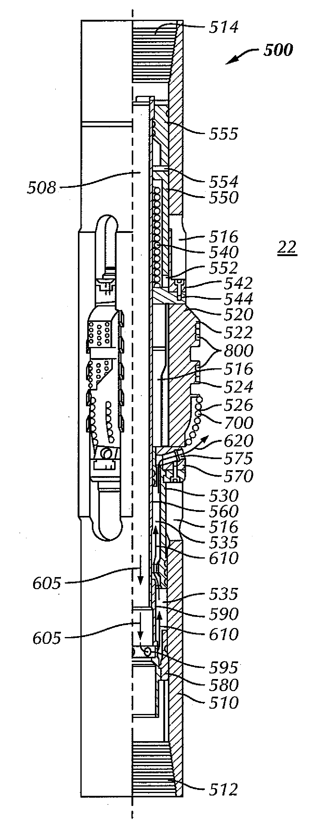
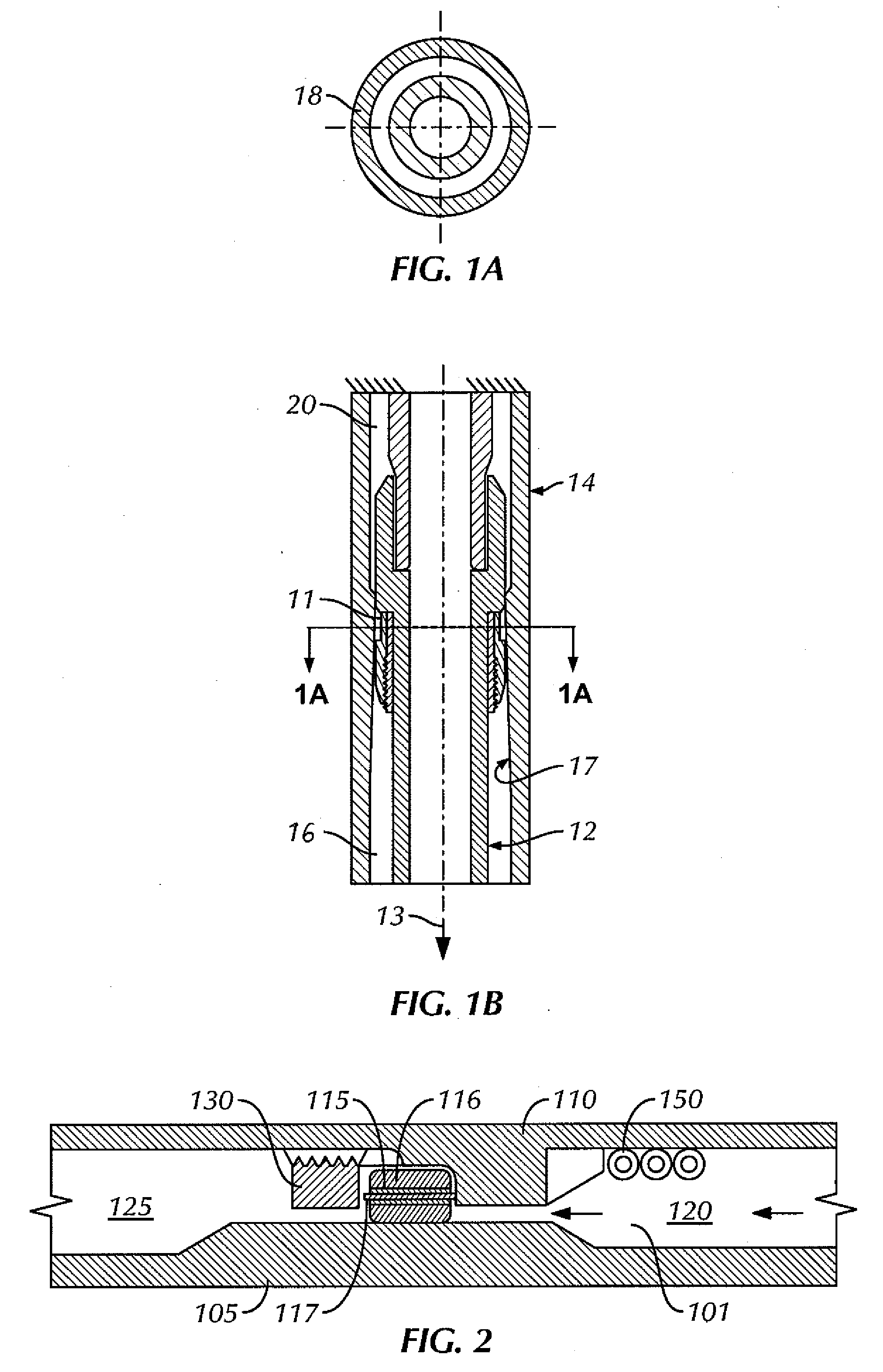
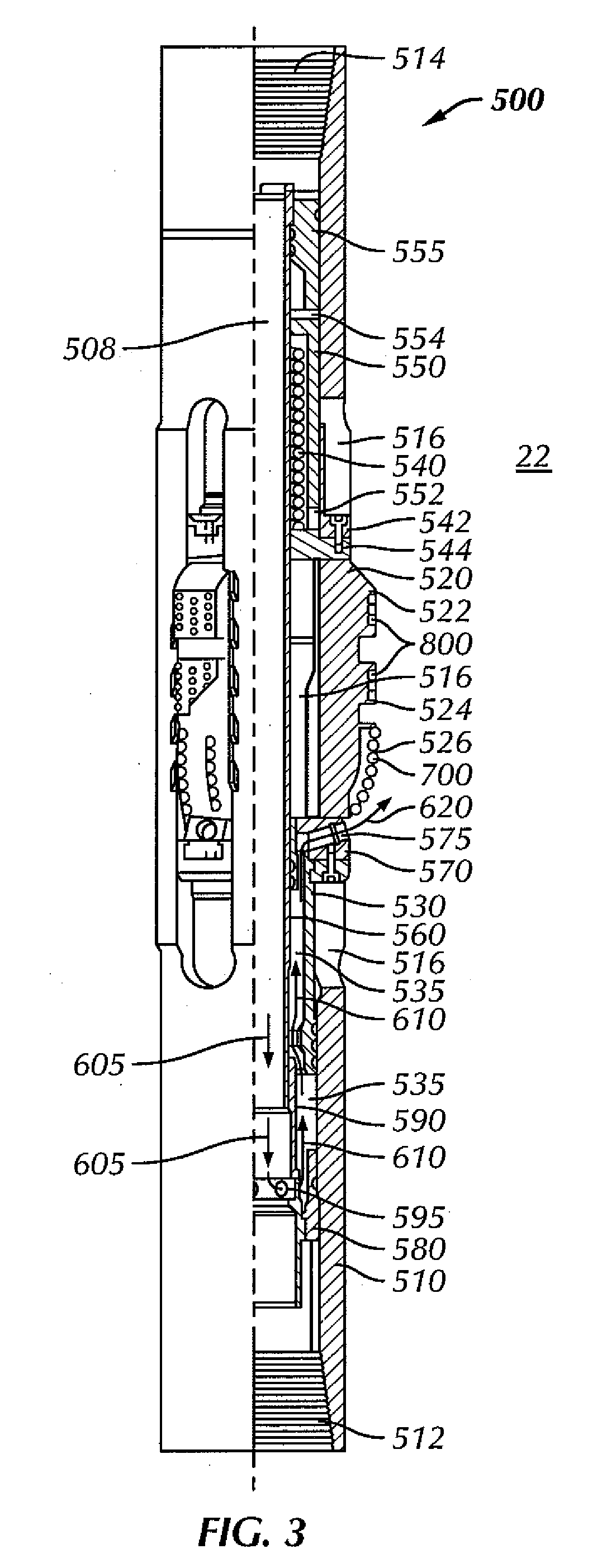
[0019]Embodiments disclosed herein are related generally to down hole tools having fluid with an adjustable viscosity, and, more specifically, to down hole tools using magnetic fields to adjust the viscosity of a magnetorheological (MR) fluid.

[0020]MR fluids are fluids that contain suspended magnetizable-particles. The carrier fluid for the suspended magnetizable-particles can be any of various fluids, including hydrocarbon-based, water-based, and silicone-based. As the name suggests, the rheological properties of MR fluids change depending on whether a magnetic field is present and the strength of the magnetic field. In particular, the apparent viscosity of the MR fluid can be controlled by modulating the magnetic field. MR fluids are commercially available from, for example, Lord Corporation (Cary, N.C.).

[0021]The magnetorheological response of MR fluids results from the polarization induced in suspended particles by the magnetic field. The interaction between the resulting induce...


PUM


Abstract

A down hole tool includes a tool body, a fluid cavity, a magnetorheological fluid disposed in the fluid cavity, and an electrical control unit in communication with the MR fluid. The electrical control unit is configured to adjust a viscosity of the MR fluid by varying a magnetic field.

Description

BACKGROUND OF INVENTION[0001]1. Field of the Invention[0002]The invention relates generally to down hole tools having fluid with an adjustable viscosity, and, more specifically, to down hole tools using magnetic fields to adjust the viscosity of a magnetorheological fluid.[0003]2. Background Art[0004]Many down hole tools used in drilling for hydrocarbons and for servicing existing wellbores to aid hydrocarbon recovery include oil or other viscous fluid to control actuation of the down hole tool. One such down hole tool is a jar.[0005]Jars are used during drilling and fishing operations to free other components of a drill string that have gotten stuck in the wellbore. Jars provide an impact blow in the up or down directions. A driller can control the jarring direction, impact intensity, and jarring times from the rig floor. The magnitude and direction of the load used to initiate the impact blow achieve this control.[0006]FIGS. 1A and 1B show cross sections through a detent portion 1...

Claims


Application Information

Patent Timeline
IPC IPC(8): E21B31/113E21B49/10
CPCE21B10/322E21B31/1135E21B17/07E21B31/107E21B34/00E21B34/066E21B33/1295
Inventor LEE, ARLEY G.
Owner SMITH INT INC
Why Eureka
Try Eureka