Vapor compression distillation system including an integrated motor/compressor unit

Active Publication Date: 2009-01-29
MECHANICAL EQUIP
View PDF6 Cites 24 Cited by
  • Summary
  • Abstract
  • Description
  • Claims
  • Application Information

AI Technical Summary

Problems solved by technology

However, the limited rotational speed of the standard motors, typically in the range of 1,450 rpm to 3,500 rpm, requires a substantially larger compressor wheel in order to develop the required pressure at the lower operating speed of the directly driven compressor wheel.

Method used


Image

  • Vapor compression distillation system including an integrated motor/compressor unit
  • Vapor compression distillation system including an integrated motor/compressor unit

Examples


Embodiment Construction

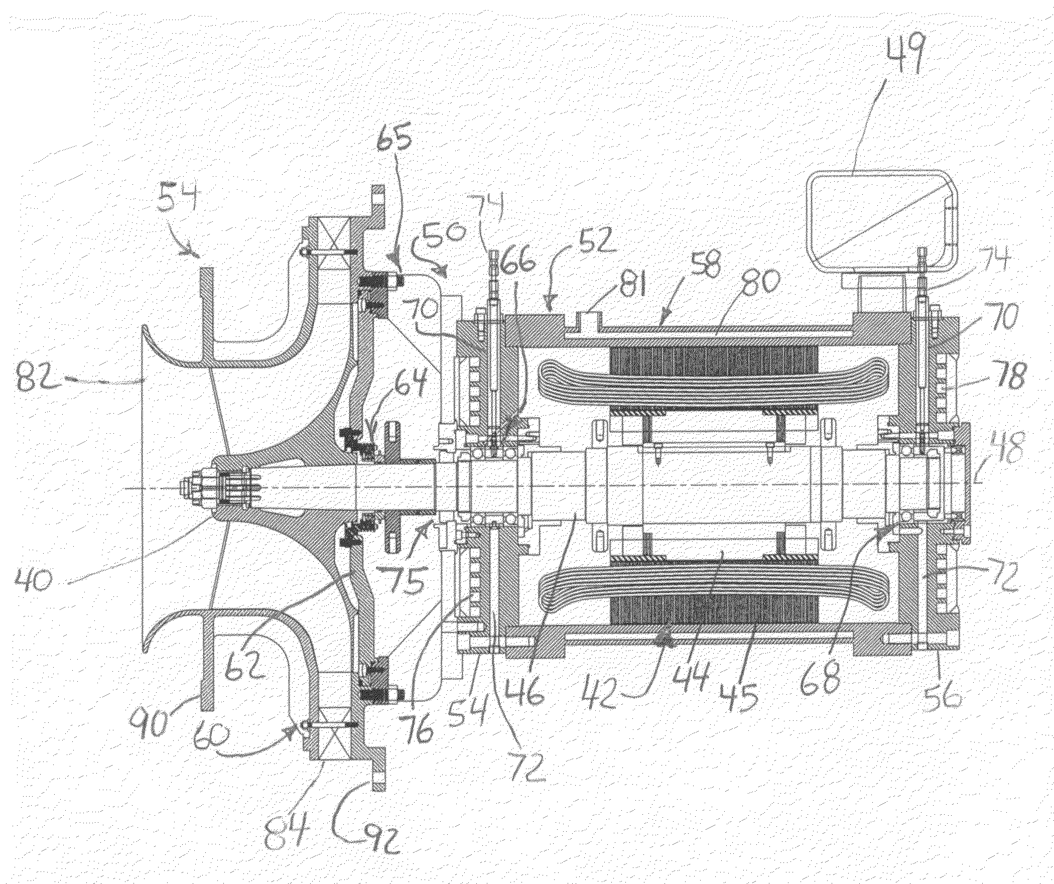
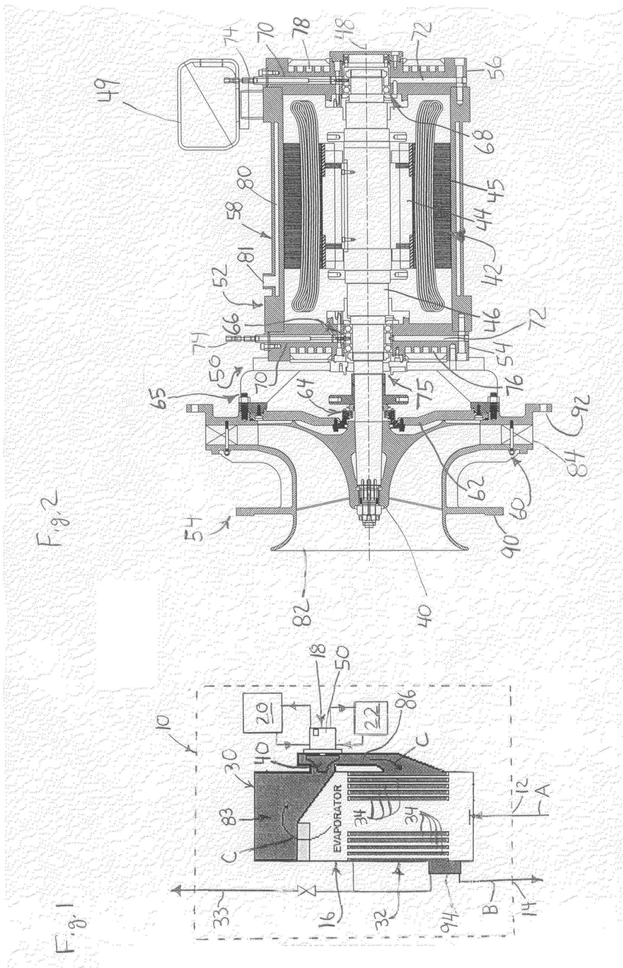
[0025]As shown in FIG. 1, a vapor compression distillation system 10 includes a fluid inlet 12 for receiving a fluid (typically water), shown generally by arrows “A”, that is to be distilled; a fluid outlet 14 for a distillate (typically distilled water), shown generally by arrows “B”, that has been distilled from the fluid; a heat exchanger 16 connected to the fluid inlet 12 and the fluid outlet 14 to transfer heat from the distillate to the fluid; and an integrated motor / compressor unit 18 connected to the heat exchanger 16 to receive vaporized distillate therefrom and to supply pressurized distillate thereto.

[0026]In some preferred embodiments, the system 10 further includes a coolant system, shown generally at 20, connected to the integrated motor / compressor 18 to supply a coolant flow thereto. The coolant system 20 can either be a non-recirculating system that draws coolant, such as water, from a suitable source, or a recirculating system that recirculates the coolant through a...


PUM


Abstract

A vapor compression distillation system (10) is provided and includes a fluid inlet (12) for receiving a fluid, a fluid outlet (14) for a distillate that has been distilled from the fluid, a heat exchanger (16) connected to the fluid inlet (12) and the fluid outlet (14) to transfer heat from the distillate to the fluid; and an integrated motor / compressor unit (18) connected to the heat exchanger (16) to receive vaporized distillate therefrom and to supply pressurized distillate thereto. The system 10 may further include a coolant system (20) connected to the integrated motor / compressor (18) to supply a coolant flow thereto. The system (10) may also include an air oil mist system (22) that is connected to the integrated motor / compressor unit (18) to supply an air oil mist thereto for bearing lubrication and cooling.

Description

CROSS-REFERENCE TO RELATED APPLICATIONS[0001]Not Applicable.FEDERALLY SPONSORED RESEARCH OR DEVELOPMENT[0002]Not Applicable.MICROFICHE / COPYRIGHT REFERENCE[0003]Not Applicable.FIELD OF THE INVENTION[0004]This invention relates to distillation processing equipment, and more specifically, to vapor compression distillation systems.BACKGROUND OF THE INVENTION[0005]Vapor compression distillation systems are known and are typically used for the desalination of sea water and for the production of pharmaceutical grade waters in accordance with U.S. Pharmacopeia and equivalent foreign standards. Examples of such systems are shown and explained in U.S. Pat. No. 5,587,054 issued Dec. 23, 1996 and titled “Vapor Compression Distillation System” and U.S. Pat. No. 6,365,005 issued Apr. 2, 2002 and titled “Apparatus and Method For Vapor Compression Distillation”.[0006]It is common for such vapor compression distillation systems to utilize high speed centrifugal compressors that are driven by a stand...

Claims


Application Information

Patent Timeline
Patent Type & Authority Applications(United States)
IPC IPC(8): B01D3/02
CPCB01D1/289F04D29/601F04D25/06B01D1/2893Y02A20/124
Inventor GSELL, GEORGE V.KLEIN, KIM C.
Owner MECHANICAL EQUIP
Why Eureka
Try Eureka