Reinforcement beam as well as method and fiber laminate for manufacturing the reinforcement beam

a technology of reinforcement beams and fiber laminates, applied in the field of reinforcement beams, can solve the problems of inability to manufacture large components such as ring frames or the like in this manner, disadvantage of a relatively large number of seams, and thickening portions in the overlap region, so as to achieve “optimum mechanical properties” and reduce the effect of weight and small radius of curvatur

Active Publication Date: 2009-01-29
AIRBUS OPERATIONS GMBH
View PDF8 Cites 29 Cited by
  • Summary
  • Abstract
  • Description
  • Claims
  • Application Information

AI Technical Summary

Benefits of technology

[0017]Using a multi-axial fiber laminate makes it possible to arrange one or several additional layers with a third fiber direction, for example with a fiber direction of 0° in particular in a peripheral area of the fiber laminate, in order to optimally receive or accept shear and / or compression forces, while the other full-area layers have, for example, a fiber direction of ±45° for ideal reception of shear and / or trans-verse forces. Other fiber direction between +20° and +70° as well as between −70° and −20° are also possible. Furthermore, use of an “endless” multi-axial areal laminate made of carbon fibers makes it possible to form spatially extended reinforcement beams, which can serve in particular as ring frames or ring frame segments. The different fiber types can be formed in view of the requirements of the reinforcement beam to be manufactured.
[0023]In accordance with this inventive method, it is possible to manufacture, for example using the “resin transfer molding” (RTM) method, a reinforcement beam of virtually any curvature, for example of a carbon fiber reinforced synthetic material, and with a cross-sectional shape that is for example L-shaped, wherein the reinforcement beam is particularly suited for receiving or accepting in its base area shear and / or transverse forces and the reinforcement beam is particularly optimized for receiving or accepting in its outer portion tensile and / or compression forces. The expression “draping” means that the base portion of the fiber laminate, in which substantially only layers with a fiber direction of ±45° are arranged, can be laid in a curved or bent manner on a support in the horizontal plane without forming creases or folds, so that also curved ring frame segments with a smaller radius of curvature can be manufactured easily.
[0024]Herein, due to the use of a virtually endless band-shaped fiber laminate, it is possible to manufacture the reinforcement beam with almost any length, in particular to manufacture large ring frames with only one joint. Reinforcement beams formed in this manner are in particular suitable as ring beam segments of various radii of curvature, that are made, for example, of carbon fiber-reinforced epoxy resin, in order to save weight. In addition, a reinforcement beam made in accordance with the inventive method has virtually “optimum mechanical properties”, due to the different directions of the fiber reinforcement in the different regions.
[0026]Due to the fact that the layers with the first and the second fiber direction are full-area layers and the layer or layers with the third fiber direction are arranged in a peripheral area of the fiber laminate, it is possible to form with the inventive areal structure, by simple folding or bending of the peripheral area to form an outer portion and subsequent draping of the remaining base portion, a reinforcement beam that can have virtually any curvature, even in the case of large geometric dimensions. Furthermore, the reinforcement beam formed with the inventive fiber laminate is suitable in particular for loads leading to shear and / or transverse forces in its base portion, while the reinforcement beam is suitable in particular for receiving tensile and / or compression forces in its outer portion, that are in particular common during flight when using the reinforcement beam as a ring frame or ring frame segment in a fuselage cell of an aircraft.

Problems solved by technology

Considerable difficulties are created in this context by the introduction of a fabric, of fiber bundles or a combination of these in order to accomplish the fiber reinforcement in the case of, for example, components that are round, oval or have the shape of a segment of a circle.
However, this leads to the disadvantage of a relatively large number of seams due to the necessary division into parts.
It is possible to reduce the number of seams with an overlapping arrangement of fabric strips, but this leads to thickened portions in the region of the overlaps.
However, such strips have the disadvantage that due to the limited width of fabric courses, they can only be fabricated with a limited length, so that larger components, such as ring frames or the like, cannot be manufactured in this manner.

Method used


Image

  • Reinforcement beam as well as method and fiber laminate for manufacturing the reinforcement beam
  • Reinforcement beam as well as method and fiber laminate for manufacturing the reinforcement beam
  • Reinforcement beam as well as method and fiber laminate for manufacturing the reinforcement beam

Examples


Embodiment Construction

[0037]The following is an explanation of an inventive reinforcement beam, a fiber laminate used for manufacturing the same, and a method for manufacturing the reinforcement beam.

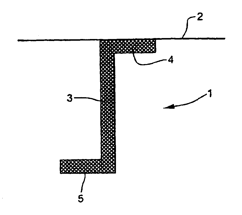
[0038]FIG. 1 is a cross-sectional view of a reinforcement beam with a Z-shaped cross section, which is used for example as a ring frame for the reinforcement of fuselage cells in aircraft.

[0039]In the embodiment shown in FIG. 1, a reinforcement beam 1 has a substantially Z-shaped cross section. The reinforcement beam 1 serves in particular to reinforce a fuselage cell (not shown in the drawings) of an aircraft and is connected with a paneling or planking 2 for this purpose. In flight, particularly shear and / or transverse forces act on a base portion 3. In an outer portion 4, the reinforcement beam 1 is mainly subjected to tensile stress, whereas in an outer portion 5 mainly compression stress arises. Moreover, the reinforcement beam 1 is also subjected to bending moments. The reinforcement beam 1 is made by ...


PUM

PropertyMeasurementUnit
angleaaaaaaaaaa
angleaaaaaaaaaa
anglesaaaaaaaaaa

Abstract

Disclosed is a reinforcement blank, in particular a curved ring frame segment for fuselage cells of aircraft, comprising a synthetic material that is reinforced by at least one fiber laminate. The fiber laminate includes at least one full-area layer with a first fiber direction and at least one full-area layer with a second fiber direction, wherein at least one further layer with a third fiber direction is arranged in a peripheral area of the fiber laminate. This results in an orientation of the fibers in the individual layers of the fiber laminate used to reinforce the reinforcement beam that is overall suitable for the applied load, so that the reinforcement beam withstands high mechanical loads at a minimum weight.

Description

FIELD OF THE INVENTION[0001]The present invention concerns a reinforcement beam, and in particular a curved ring frame segment for fuselage cells of aircraft, comprising a synthetic material that is reinforced by at least one fiber laminate.BACKGROUND OF THE INVENTION[0002]Furthermore, the present invention concerns a method for manufacturing a reinforcement beam, in particular of a curved ring frame segment, for a fuselage cell of an aircraft comprising a synthetic material that is reinforced by at least one fiber laminate.[0003]Furthermore, the present invention concerns a fiber laminate for manufacturing a reinforcement beam, in particular of a ring frame segment, wherein the fiber laminate comprises at least one layer with a first fiber direction and at least one layer with a second fiber direction as well as a further layer with a third fiber direction.[0004]Ordinarily, ring frames are used in airplanes to reinforce the fuselage cells. These ring frames are mostly made of alumi...

Claims


Application Information

Patent Timeline
Patent Type & Authority Applications(United States)
IPC IPC(8): B64C1/06B05D3/12
CPCB29C70/205B29C70/48B64C1/061Y02T50/433B64C1/065B64C2001/0072B64C1/064B29D99/0003Y02T50/40
Inventor EDELMANN, KLAUSBOLD, JENS
Owner AIRBUS OPERATIONS GMBH
Why Eureka
Try Eureka