Measurement apparatus and a method of using measurement apparatus

a measurement apparatus and measurement technology, applied in the field of industrial metrology, can solve the problems of reducing upfront cost, and achieve the effects of reducing financial risk, reducing upfront cost, and increasing the market for measurement probe systems

Inactive Publication Date: 2009-01-29
RENISHAW PLC
View PDF22 Cites 12 Cited by
  • Summary
  • Abstract
  • Description
  • Claims
  • Application Information

AI Technical Summary

Benefits of technology

[0029]In summary, the present invention offers the potential to increase the market for measurement probe systems without having to compromise on the accuracy or quality of such systems. From a user's

Problems solved by technology

Although it is known to provide hire purchase or loan arrangements that allow the purchase cost to be spread over a longer period, suc

Method used


Image

  • Measurement apparatus and a method of using measurement apparatus
  • Measurement apparatus and a method of using measurement apparatus

Examples


Embodiment Construction

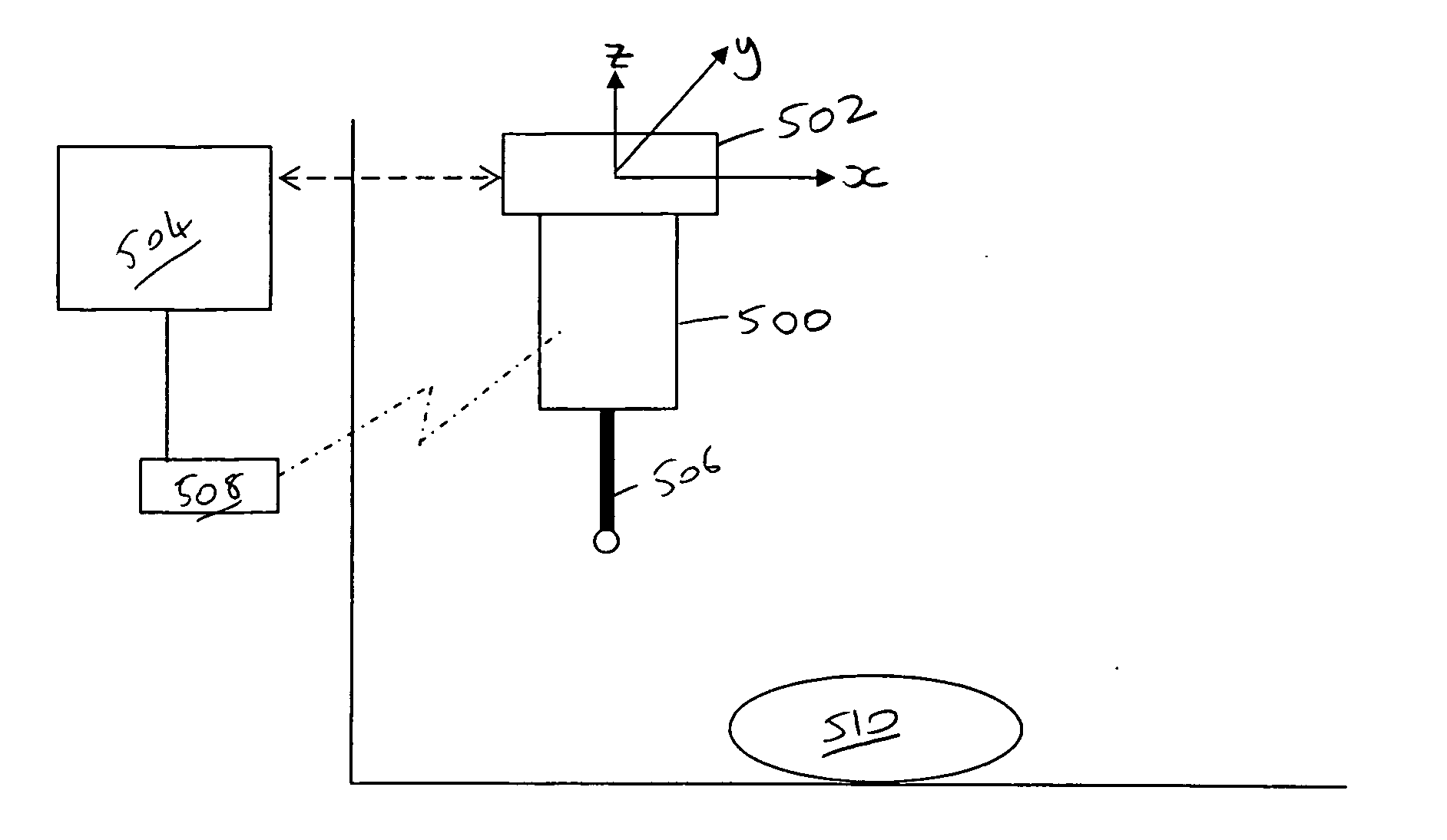
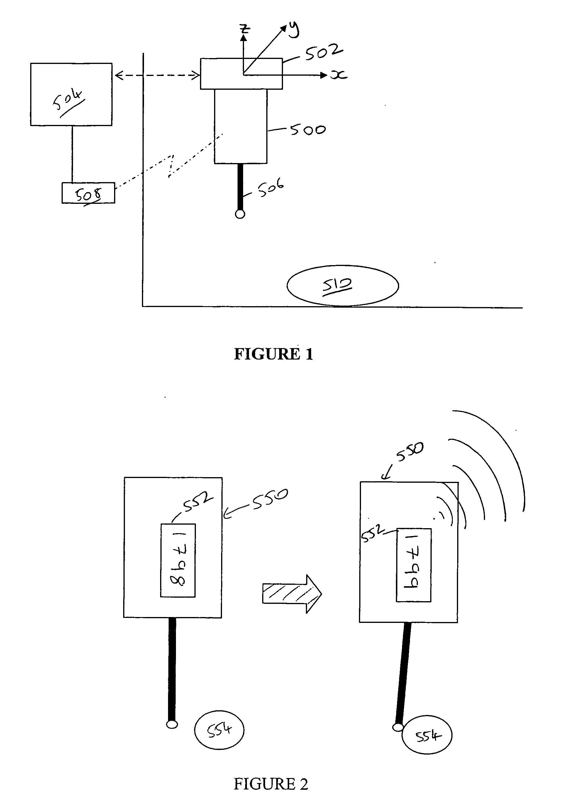
[0033]Referring to FIG. 1, a measurement probe 500 is shown mounted to the spindle 502 of a machine tool. The spindle 502 is moveable in three dimensions (X, Y, Z) under the control of a computer controller 504. The machine tool also comprises, in a known manner, various position encoders that accurately measure the position (in X,Y,Z) of the spindle 502 and pass such position information back to the controller 504. Various alternative types of machine tool are also known.

[0034]The measurement probe 500 is a touch trigger probe in which the stylus holder is attached to the probe body by a spring-loaded kinematic arrangement of the type originally described in U.S. Pat. No. 4,153,998, the contents of which are hereby incorporated by reference. In use, a workpiece contacting stylus 506 is brought into contact with an object 510 to be measured. Deflection of the stylus 506 unseats the stylus holder from the probe body thereby breaking an electrical circuit. A processor is provided as p...


PUM


Abstract

A method of measurement using a measurement probe system includes the steps of (i) providing a measurement probe system having a measurement probe to a user, the measurement probe system being suitable for use with co-ordinate positioning apparatus and (ii) monitoring usage of the measurement probe system.

Description

[0001]This nonprovisional application claims the benefit of U.S. Provisional Application No. 60 / 996,984, filed Dec. 13, 2007. This application also claims priority from European patent application 07252959.7 filed Jul. 26, 2007 and from European patent application 07252965.4 filed Jul. 26, 2007. The disclosure of each of the provisional application and of the two listed priority European applications is incorporated herein by reference in its entirety.INTRODUCTION[0002]The present invention relates to measurement apparatus and to methods of using such measurement apparatus. In particular, the invention relates to measurement probes and methods of use thereof.BACKGROUND OF THE INVENTION[0003]In the field of industrial metrology, it is known to use co-ordinate positioning apparatus to accurately measure or inspect the dimensions of an object such as a workpiece. To perform such a measurement function, co-ordinate positioning apparatus moves a measurement probe around within the workin...

Claims


Application Information

Patent Timeline
IPC IPC(8): G07C3/00G01B5/00
CPCG01B5/012G01B21/047G01B5/008G01B5/02G01B2210/58
Inventor PRESTIDGE, TIMFUGE, JONATHAN P.LUMMES, STEPHEN E.CAMPBELL, STUART K.
Owner RENISHAW PLC
Why Eureka
Try Eureka