Heat-treating furnace

a heat treatment furnace and heat treatment technology, applied in the field of heat treatment furnaces, can solve the problems of increasing equipment and cost, difficult to use for binder removal, limited operating conditions of the furnace, etc., and achieve the effect of optimum design for the operating conditions, and preventing peeling and breakage of the heat insulator

Active Publication Date: 2009-01-29
MURATA MFG CO LTD
View PDF18 Cites 16 Cited by
  • Summary
  • Abstract
  • Description
  • Claims
  • Application Information

AI Technical Summary

Benefits of technology

[0039]When the reflector has a structure in which a plurality of thin plates composed of a metal material with heat resistance is disposed so that the main surfaces of the thin plates are arranged in parallel to each other with a predetermined space between the adjacent main surfaces, it is possible to securely prevent the binder vapor produced in a binder removing step from condensing and solidifying in the heat insulator and prevent peeling and breakage of the heat insulator due to deterioration, for example, when a ceramic molding containing a binder is fired. Therefore, the heat treating furnace can be made more effective.
[0040]In addition, the temperature of the back of the heat insulator (the temperature of the peripheral surface of the heat insulator which faces the reflector) can be controlled by controlling the number of the thin plates constituting the reflector and composed of a metal material with heat resistance, thereby permitting optimum design for the operating conditions of the heat treating furnace.
[0041]Further, the surface temperature of the reflector can be set to a desired value by appropriately determining the thickness of the heat insulator and the number of the thin plates constituting the reflector for the furnace temperature. As a result, even when the atmosphere in the furnace is an oxidizing atmosphere, the need for an expensive material as a constituent material of the reflector can be eliminated, thereby achieving an economically desired insulation effect.
[0042]When partition heat insulators are disposed in the heat treating furnace between the respective thin plates constituting the reflector, for suppressing gas convections between the respective thin plates, gas convections present between the respective thin plates can be prevented by the partition heat insulators, and convections occur in predetermined regions partitioned by the partition heat insulators. Therefore, the heat insulation efficiency of the reflector can be improved.
[0043]Further, for example, when partition heat insulators are respectively disposed substantially parallel to the upper side and the lower side of the thin plates which constitute the reflector vertically disposed, a region where convection occurs is decreased as the distance between the upper and lower partition heat insulators is decreased. Therefore, convective heat transfer can be suppressed, improving the heat insulation efficiency.
[0044]When the reflector is disposed to cover substantially the entire peripheral surface of the heat insulator, it is possible to securely prevent the binder vapor produced in a binder removing step from condensing and solidifying in the heat insulator and also prevent peeling and breakage of the heat insulator due to deterioration, for example, when a ceramic molding containing a binder is fired. Therefore, the heat treating furnace can be made more effective.

Problems solved by technology

However, such a firing furnace is mainly used for firing a ceramic molding after the binder removing step and is generally difficult to use for binder removal.
However, the heat treating furnace requires not only the inner case disposed in the furnace body but also the outlet tube 76 and the impurity collecting trap 75, and thus the configuration is complicated and causes the problem of increasing the size of equipment and cost.
Although a heat treating furnace including a case with the inner wall covered with a metal muffle is also known, covering the inner wall of the case with the metal muffle has the following problems:
The maximum operating temperature depends on the heat resistance temperature of a metal which constitutes the metal muffle, and thus the operating conditions of the furnace are limited.
A measure against creep deformation of the metal which constitutes the metal muffle is required, and thus the inner dimensions of the furnace are limited.
The furnace has a double structure, and thus much time is required for assembly and manufacture, thereby increasing the cost.
The condensed vapor permeates into the heat insulator and solidifies therein to cause the problem of not only increasing the thermal conductivity of the heat insulator but also producing a large difference in thermal conductivity between a portion in which the vapor permeates and a portion in which the vapor does not permeate, causing peeling and breakage of the heat insulator.
In particular, when a module heater having a metal heater embedded in a heat insulator is used, there is the problem of decreasing the insulation of the metal heater embedded in the heat insulator within a short time.
That is, in a conventional heat treating furnace, a module heater is a firing heater and cannot be used directly for degreasing, and an inner case is required when the module heater is also used for degreasing.

Method used


Image

  • Heat-treating furnace
  • Heat-treating furnace
  • Heat-treating furnace

Examples


embodiment 1

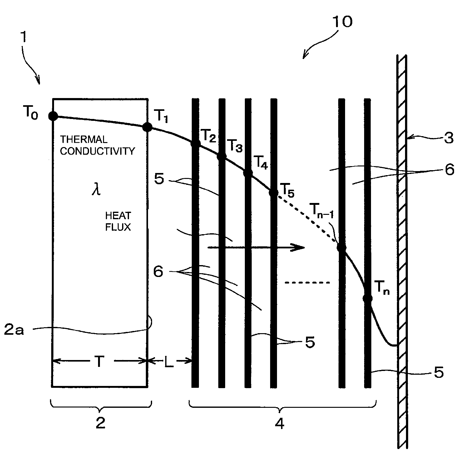
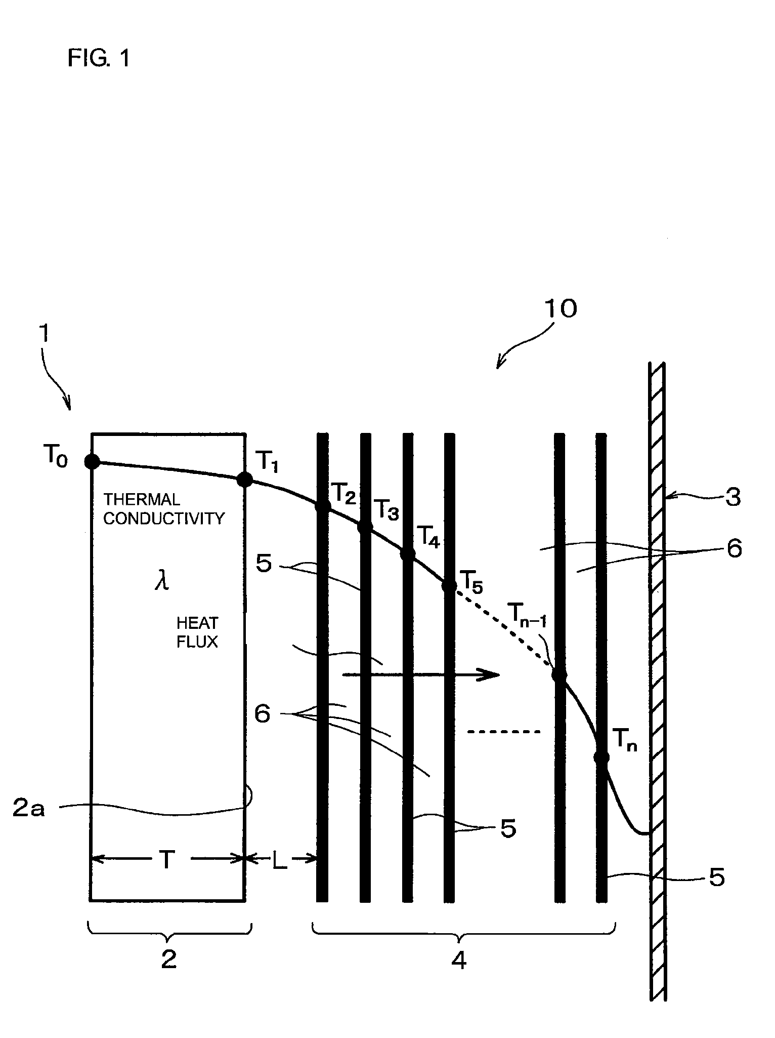
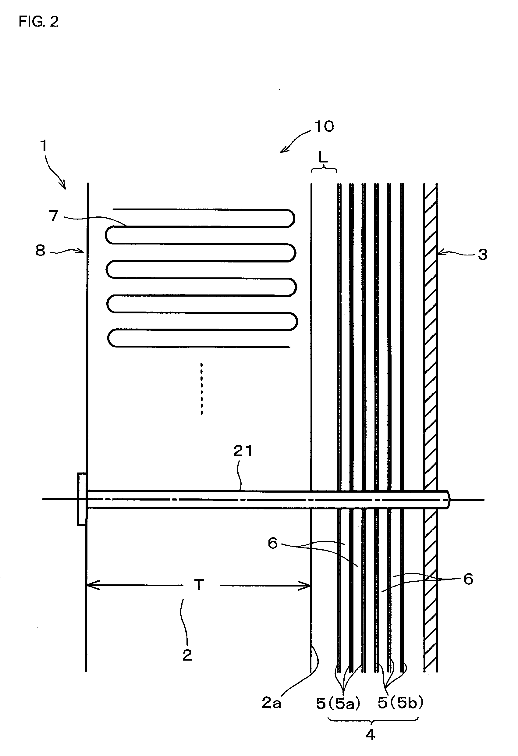
[0089]FIGS. 2 to 4 are drawings each showing a configuration of a heat treating furnace according to an embodiment (Embodiment 1). FIG. 2 is a sectional view showing a principal configuration. FIG. 3 is a sectional front view schematically showing a configuration of a heat treating furnace. FIG. 4 is a sectional plan view schematically showing a configuration of a heat treating furnace.

[0090]A heat treating furnace 10 is one for continuously performing a degreasing step and a sintering step for a ceramic laminate for a ceramic multilayer substrate using low-temperature sinterable ceramic green sheets. A material to be heat-treated by the heat treating furnace is a ceramic laminate prepared by laminating thin ceramic green sheets and contains about 20% by weight of a binder.

[0091]As schematically shown in FIG. 2, the heat treating furnace used in Embodiment 1 includes a case 3 provided with a heat treatment region 1 for receiving therein the material to be heat-treated and a front do...

embodiment 2

[0105]FIG. 5 is a drawing showing a principal portion of a heat treating furnace according to another embodiment (Embodiment 2).

[0106]In the heat treating furnace of Embodiment 2, partition heat insulators 12a and 12b are disposed on both the upper and lower sides of the spaces between the plurality of thin plates 5, which constitute a reflector 4, so as to be substantially parallel to the upper side 15 and the lower side 16 of the thin plates 5, for suppressing the passage of gas between the respective thin plates 5. The other configuration is the same as in the heat treating surface of Embodiment 1.

[0107]In FIG. 5, the portion denoted by the same reference numeral as in FIGS. 1 to 4 is the same as or corresponds to FIGS. 1 to 4.

[0108]As in the heat treating furnace of Embodiment 2, when partition heat insulators 12a and 12b are disposed on the upper and lower sides of the spaces between the plurality of thin plates 5, which constitute a reflector 4, so as to be substantially paral...


PUM

PropertyMeasurementUnit
temperatureaaaaaaaaaa

Abstract

A heat treating furnace capable of continuously performing binder removal and subsequent firing without requiring a complicated configuration and increasing the equipment size and cost, for example, for degreasing a ceramic molding which is to be fired in a process for manufacturing a ceramic electronic component. A heat insulator is disposed to surround a heat treatment region in a case, and a reflector is disposed between the inner wall of the case and the insulator in order to reflect heat transferred from the heat treatment region through the heat insulator. A module heater including a heater embedded in the insulator is used. As the reflector, there is used a reflector having a structure in which a plurality of thin plates is arranged so that the main surfaces are arranged in parallel to each other with a predetermined space between the adjacent main surfaces.

Description

CROSS-REFERENCE TO RELATED APPLICATIONS[0001]This is a continuation under 35 U.S.C. § 111(a) of PCT / JP2007 / 055410 filed Mar. 16, 2007, and claims priority of JP2006-081539 filed Mar. 23, 2006, both incorporated by reference.BACKGROUND[0002]1. Technical Field[0003]The present disclosure relates to a heat treating furnace, and more particularly to a heat-treating furnace, such as a firing furnace, a degreasing furnace, or the like, for heat-treating a material to be heat-treated, including a step of firing a green ceramic body and a step of removing a binder before the firing step, for example, in the manufacture of ceramic electronic components.[0004]2. Background Art[0005]FIG. 6 is a drawing showing an example of a conventional heat-treating furnace. In general, a firing furnace including a so-called module heater 64 which includes a heater 63 disposed in a heat insulator 62, such as a ceramic wool material, around a heat-treatment region 65 in a case 61 as schematically shown in FI...

Claims


Application Information

Patent Timeline
Patent Type & Authority Applications(United States)
IPC IPC(8): F27D1/00
CPCB22F3/003B22F2998/00F27B17/0016F27B17/0075F27D1/0006H05K1/0306H05K3/4629H05K3/4611B22F3/1021B32B18/00C04B35/638C04B35/64
Inventor OHARA, TAKASHI
Owner MURATA MFG CO LTD
Why Eureka
Try Eureka