Pressure relief valve for structure

a pressure relief valve and structure technology, applied in the field of structures, can solve the problems of severe building damage, roof blowing off, and building wind damage, and achieve the effects of reducing the possibility, reducing the possibility, and instant relief of windstorm-induced pressure insid

Inactive Publication Date: 2009-01-29
REED ROBERT S
View PDF16 Cites 3 Cited by
  • Summary
  • Abstract
  • Description
  • Claims
  • Application Information

AI Technical Summary

Benefits of technology

[0011]Accordingly, it is an object of the present invention to provide a pressure relief valve for structure which is capable of instantly relieving windstorm-induced pressure interior to a structure. Design features allowing this object to be accomplished include a plurality of springs urging a valve into a valve seat, the springs being sized to permit the valve to open when a pre-determined pressure differential between air pressure exterior to the structure and air pressure interior to the structure has been reached, e.g. 1.5 pounds per square inch (“psi”). Benefits associated with the accomplishment of this object include reduction of the possibility of the roof being blown off the structure due to windstorm-induced pressure interior to a structure, and the attendant cost savings in repair.
[0012]It is another object of the present invention to provide a pressure relief valve for structure which is normally closed. Design features allowing this object to be accomplished include a plurality of springs urging a valve into a valve seat. Advantages associated with the accomplishment of this object include reduced entry of precipitation, and reduced attendant water damage to the structure.
[0013]It is still another object of this invention to provide a pressure relief valve for structure whose up-wind side will tend to remain closed while its down-wind side opens to relieve pressure interior to a structure. Design features enabling the accomplishment of this object include a valve having spoiler along its edge(s), which spoils the smooth airflow like ice on an airplane wing destroys lift, thus causing the storm wind itself to urge the valve upwind side to remain closed.
[0014]Advantages associated with the realization of this object include less entry of wind-driven precipitation into the structure (because the valve opens for only seconds in a tornado), and the associated reduced water damage and lower cost of repair.
[0015]It is another object of the present invention to provide a pressure relief valve for structure which may be installed in a single location. Design features allowing this object to be accomplished include a valve seat disposed around a building valve aperture, and a plurality of springs urging a valve into the valve seat. Benefits associated with the accomplishment of this object include instantaneous speed, simpler and lest costly installation, better reliability, and reduced maintenance cost.
[0016]It is still another object of this invention to provide a pressure relief valve for structure which may be secured in place using a single cable. Design features enabling the accomplishment of this object include a single cable entering and exiting a valve seat and valve through a plurality of springs. Advantages associated with the realization of this object include simpler construction, along with the associated reduction in cost.

Problems solved by technology

The internal air pressure literally blows the roof off of the structure.
In this scenario, severe building damage results, clearly from the loss of the roof itself, but also from the ensuing water damage caused by the frequently torrential rain which falls directly into the structure.
The problem of wind damage to buildings will probably get worse in the future, due to the natural hurricane cycle, which is currently on the ascendancy, and also due to increased storm strength due to global warning.
While this approach apparently relieved inside pressure, it was cumbersome to install the requisite valves at various locations in the structure to be protected, was very slow for tornados, and lacked the very high quality flow required for timely pressure equalization.
This vent was permanently open, and appeared to suffer from the disadvantage that rain could enter the structure, given sufficient wind.
While these designs appeared capable of relieving pressure internal to a building, no means for doing so on the down-wind side was taught, because these valves could not change their angle relative to the roof upon which they were mounted.

Method used


Image

  • Pressure relief valve for structure
  • Pressure relief valve for structure
  • Pressure relief valve for structure

Examples


Embodiment Construction

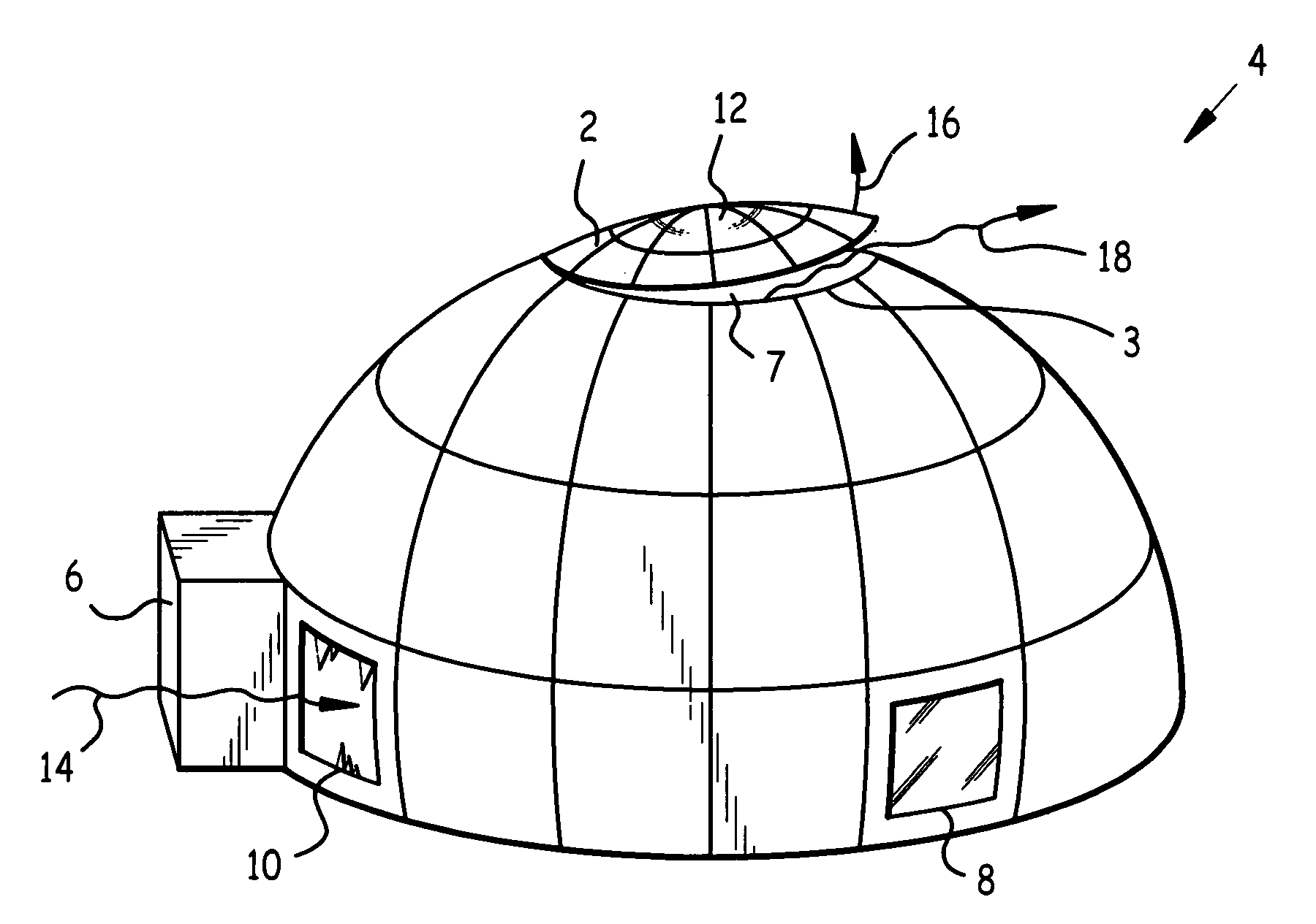
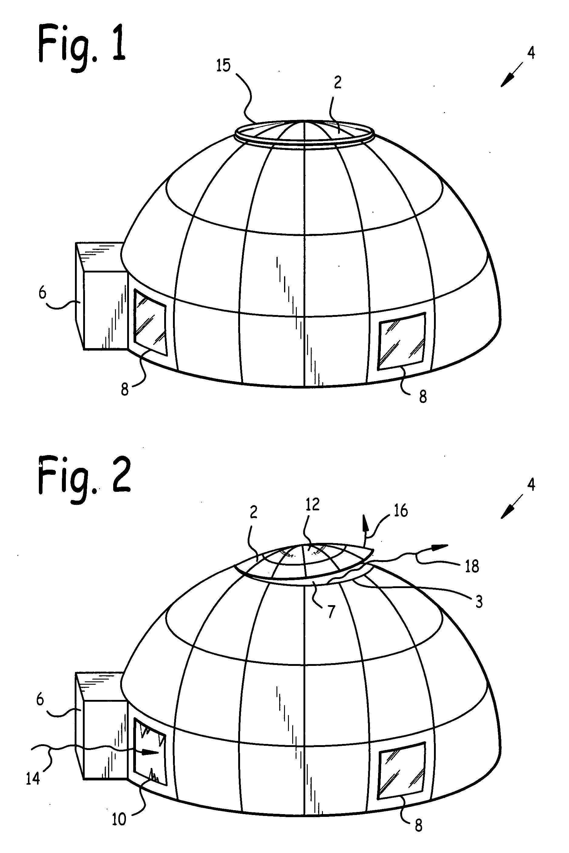
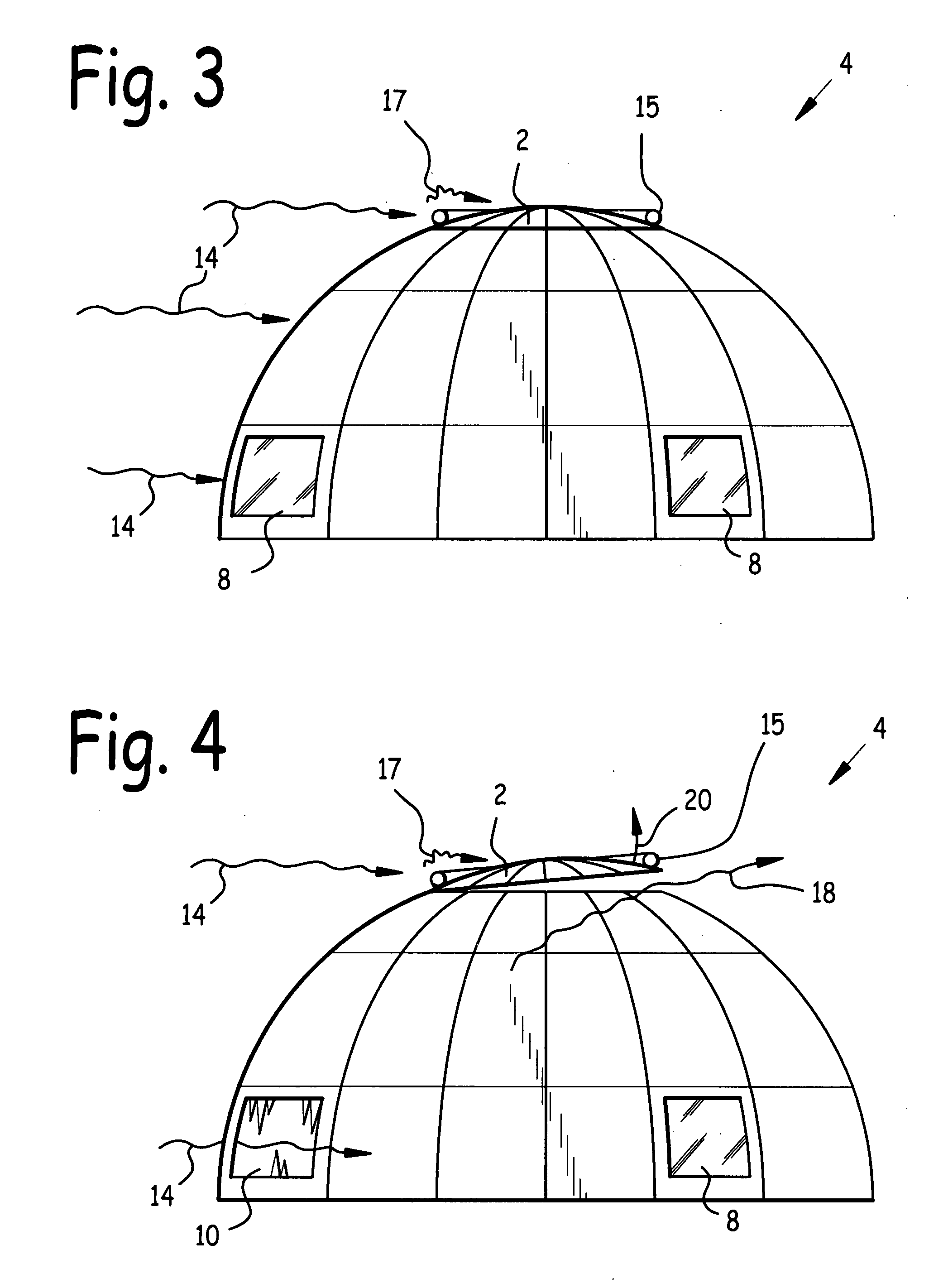
[0029]Referring now to FIG. 1, we observe a side isometric view of a pressure relief valve 2 mounted at the top of structure 4. Structure 4 comprises door 6 and windows 8. FIG. 2 is a side isometric view of valve 2 which has opened to relieve air pressure internal to structure 4. As may be observed in FIG. 2, valve 2 seats in valve seat 3, which is disposed around structure valve aperture 7. Spoiler 15 is disposed around the edge of valve 2. Unless opened by internal pressure within structure 4, valve 2 is normally spring-loaded, and / or urged by gravity, into the closed position depicted in FIG. 1. In the preferred embodiment, an internal structure pressure of as little as 1.5 pounds per square inch (psi) sufficed to open valve 2.

[0030]Referring now to FIG. 2, storm wind 14 has breached a window 8 such as may occur during a hurricane, and is now blowing into structure 4 via broken window 10. Valve 2 has opened against its spring-loaded mounting as indicated by arrow 16, and is permi...


PUM


Abstract

A pressure relief valve for structure. A valve with a spoiler around its edge sits in a valve seat around a structure valve aperture, and is spring-loaded into a closed position. Storm wind entering the structure through a breached window, door, or other structure opening escapes through the valve, which opens when exposed to a pressure differential of approximately 1.5 psi. Lift created by storm wind impinging on the spoiler tends to urge the upwind side of the valve closed. The valve may incorporate a skylight. In the preferred embodiment, the shape of the valve was a spherical or spheroid section, and the spring-loading was provided by a plurality of spring assemblies disposed around the edge(s) of the valve.

Description

BACKGROUND OF THE INVENTION[0001]1. Field of the Invention[0002]This invention relates to structures, and in particular to a pressure relief valve for structure.[0003]2. Background of the Invention[0004]A common destruction sequence for building structures during windstorms such as hurricanes and tornadoes involves the following steps: 1. An opening such as a window or door is blown in on the upwind side of the structure; 2. The pressure of the air inside the building rises due to strong wind entering the breached opening; and 3. The internal air pressure literally blows the roof off of the structure. In the case of a tornado, the building actually explodes due to the sudden pressure differential of air trapped inside vs. the greatly reduced air pressure outdoors as the tornado approaches closely.[0005]In this scenario, severe building damage results, clearly from the loss of the roof itself, but also from the ensuing water damage caused by the frequently torrential rain which falls...

Claims


Application Information

Patent Timeline
Patent Type & Authority Applications(United States)
IPC IPC(8): F24F7/02
CPCE04D13/03E04H9/14F24F7/02F16K17/006F16K17/00Y02A50/00
Inventor REED, ROBERT S.
Owner REED ROBERT S
Why Eureka
Try Eureka